Eureka AIR delivers breakthrough ideas for toughest innovation challenges, trusted by R&D personnel around the world.

Wire dress cover

Active Publication Date: 2015-11-17
TYCO ELECTRONICS BRASIL
View PDF9 Cites 6 Cited by
  • Summary
  • Abstract
  • Description
  • Claims
  • Application Information

AI Technical Summary

Benefits of technology

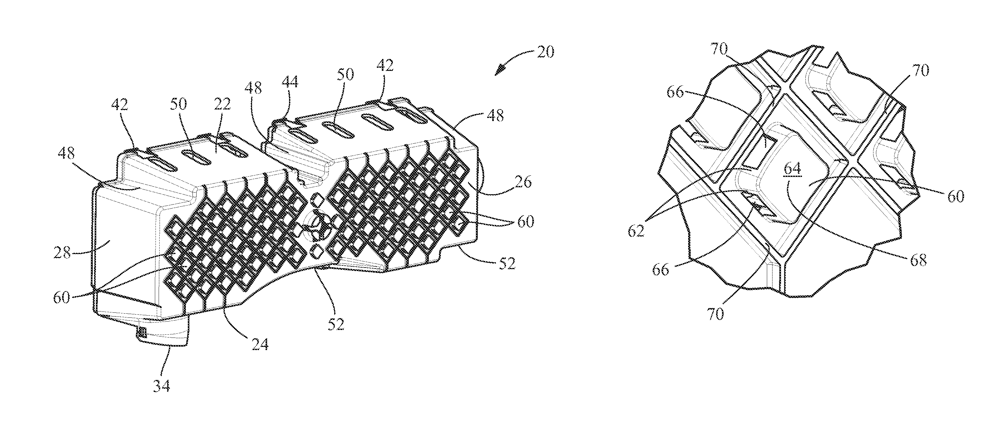
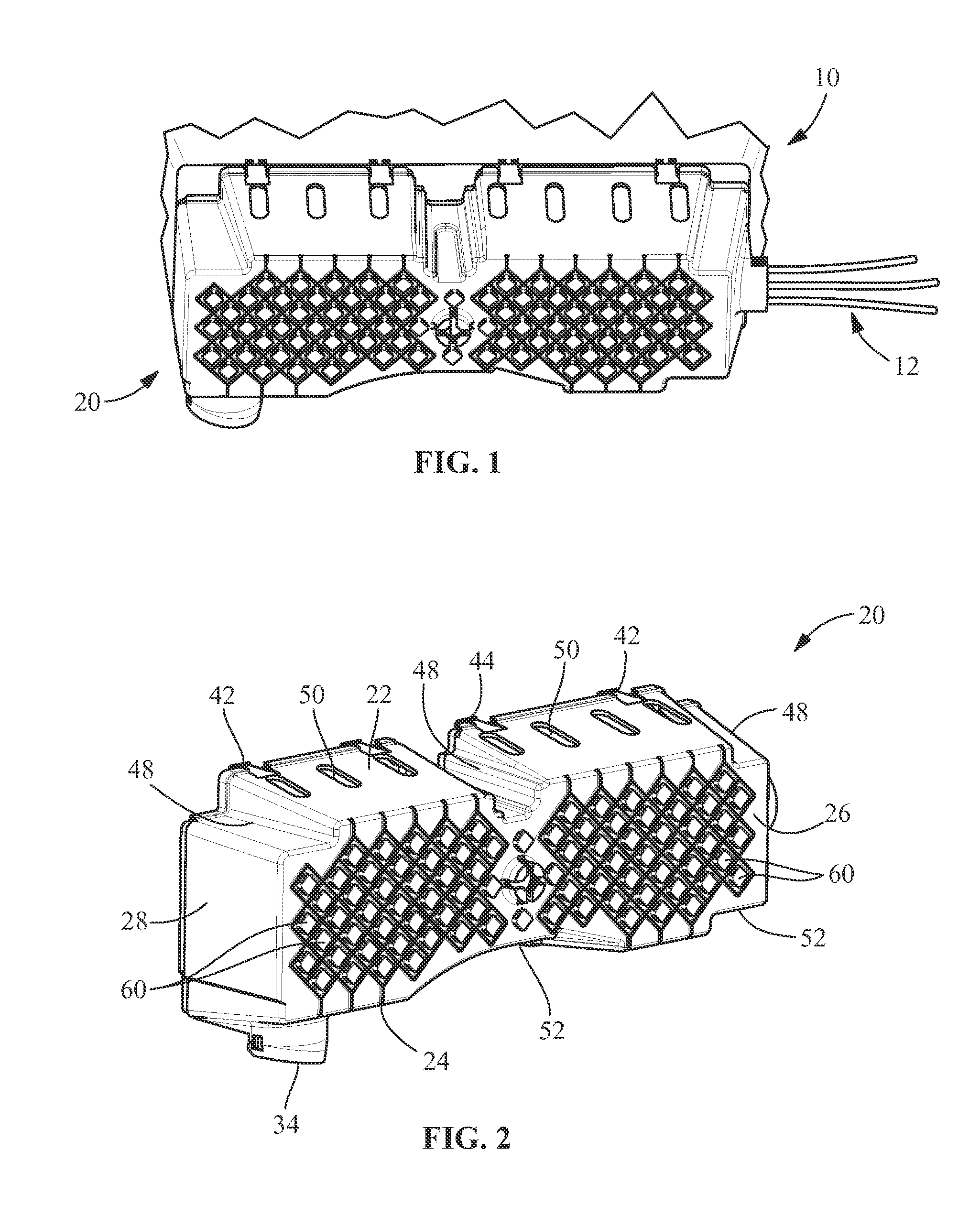
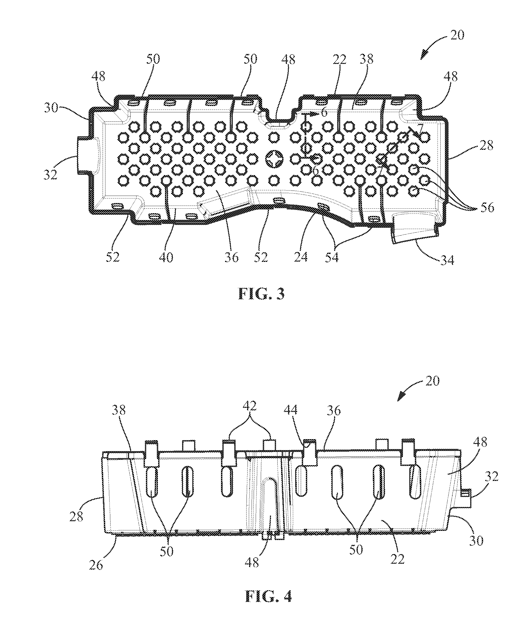
The invention is a wire dress cover for an electrical connector that allows for heat dissipation while protecting the wires and electrical terminations. The cover has heat dissipating openings and guards with side and top walls to deter material from entering the cover. The guards also have curved top surfaces to deflect water droplets away from the openings. The technical effect of the invention is to provide better protection and preventive measures against overheating and damage to the wires.

Problems solved by technology

These forces can damage the electrical terminations of the wires to the terminals in the housings of the connectors.
Electrical connectors with a large number of wires are particularly susceptible to having damaged electrical terminations within the connector housing.
For example, wires from one connector may tangle with wires from other connectors such that the movement of any one connector may damage the termination of wires in other connectors.
The tangling of wires can also make the tracing of wires during troubleshooting operations difficult to achieve.
Covers of this type generally are effective, but complicate the termination and assembly process.
Repairs or replacement of damaged or defective leads after termination and insertion is similarly complicated by the need to extract one lead from the aperture in the cover and insert another lead therethrough.
This is particularly difficult if the cover tightly engages the wires to contribute to either sealing or strain relief.
However, as electronic devices and connectors become more sophisticated, more current and more electrical terminations are required, thereby generating more heat in the wires and at the electrical terminations.
Most of these prior art wire dress covers have not been constructed to provide sufficient heat exchange or heat dissipation.

Method used


Image

  • Wire dress cover
  • Wire dress cover
  • Wire dress cover

Examples


Embodiment Construction

[0020]The description of illustrative embodiments according to principles of the present invention is intended to be read in connection with the accompanying drawings, which are to be considered part of the entire written description. In the description of embodiments of the invention disclosed herein, any reference to direction or orientation is merely intended for convenience of description and is not intended in any way to limit the scope of the present invention. Relative terms such as “lower,”“upper,”“horizontal,”“vertical,”“above,”“below,”“up,”“down,”“top” and “bottom” as well as derivatives thereof (e.g., “horizontally,”“downwardly,”“upwardly,” etc.) should be construed to refer to the orientation as then described or as shown in the drawing under discussion. These relative terms are for convenience of description only and do not require that the apparatus be constructed or operated in a particular orientation unless explicitly indicated as such. Terms such as “attached,”“aff...


PUM


Abstract

A wire dress cover for an electrical connector. The wire dress cover includes a rear wall with heat dissipating openings which extend therethrough. Side walls and end walls extend from the rear wall. At least one wire receiving opening is provided in the side walls or the end walls. Guards are positioned proximate the heat dissipating openings. The guards have guard side walls with side wall openings which extend therethrough. Top walls of the guards extend from the guard side walls. The top walls extend over at least a portion of the heat dissipating openings. The heat dissipating openings and the side wall openings allow for heat generated inside the wire dress cover to be dissipated to the outside of the wire dress cover, while the top walls of the guards deter material from entering the inside of the wire dress cover.

Description

FIELD OF THE INVENTION[0001]The present invention is directed to a wire dress cover which protects the wires and terminals from damage due to water splash while providing for effective heat exchange.BACKGROUND OF THE INVENTION[0002]Many electrical connectors are employed in environments where forces may be exerted on the wires which extend from the electrical connectors. These forces can damage the electrical terminations of the wires to the terminals in the housings of the connectors. Electrical connectors with a large number of wires are particularly susceptible to having damaged electrical terminations within the connector housing. For example, wires from one connector may tangle with wires from other connectors such that the movement of any one connector may damage the termination of wires in other connectors. The tangling of wires can also make the tracing of wires during troubleshooting operations difficult to achieve.[0003]Prior art electrical connectors have employed covers,...

Claims


Application Information

Patent Timeline
IPC IPC(8): H01R13/58H05K7/20H01R13/52
CPCH05K7/2039H01R13/5213H01R13/58H01R13/5208H01R13/5227
Inventor CAVALLIERI, AMADEU LUIZ FAZANIGOLDSCHMIDT, JOSE ROBERTO
Owner TYCO ELECTRONICS BRASIL
Why Eureka
Eureka Blog
Learn More