Programmable tucking attachment for a sewing machine and method

Inactive Publication Date: 2005-05-10
L & P PROPERTY MANAGEMENT CO
View PDF24 Cites 8 Cited by
  • Summary
  • Abstract
  • Description
  • Claims
  • Application Information

AI Technical Summary

Benefits of technology

[0009]The present invention provides a tucking attachment for a sewing machine that facilitates sewing one material to another around a corner. The tucking attachment of the present invention permits tucks of different lengths to be formed in a material. Therefore, the tucking attachment of the present invention provides great flexibility in controlling the fullness of material in sewing around a corner as well as the appearance and style of the finished material. Further, with the tucking attachment of the present invention, the formation of each tuck is automatically and precisely controlled; and therefore, the formation of tucks around a corner is repeatable from corner to corner. The tucking attachment of the present invention automatically creates material tucks so that the material can be guided to sew a seam around a corner with a minimum of operator intervention; and therefore, high quality material corners can be sewn without substantially increasing the manufacturing costs.
[0011]According to the principles of the present invention and in accordance with the described embodiments, the invention provides a tucking attachment for a sewing machine. The tucking attachment has a tucking blade with one end positioned adjacent the material and a tucking blade drive with an output shaft mechanically coupled to the tucking blade. A control, connected to the tucking blade drive, has a memory storing programmable displacements of the tucking blade and is operable to command the tucking blade drive to move the tucking blade through a programmable displacement to form a tuck in the material adjacent a presser foot of the sewing machine. Thereafter, the control is operable to command the tucking blade drive to move the tucking blade in an opposite direction. Thus, repeating the above cycle of operation permits successive tucks of different lengths to be formed in the material, thereby facilitating sewing a curved seam in the material.

Problems solved by technology

One such challenge is the sewing of the components at their respective corners.
However, all of those techniques require various manual operations, and therefore, incorporating the gusset into pillow-top mattresses normally makes them more expensive to manufacture than conventional mattresses.
However, due to the nature and construction of the mattress cover material and of the gusset material, often the gussets and panels shrink or change shape at differing rates if left to sit, thus somewhat altering the location of the pre-mitered corner on the gusset material with respect to the corner on the mattress panel.
This adjustment results in extra operator time, as well as the possibility that the mitered corner is not properly positioned, or that the corner exhibits an uneven or undesired appearance.
Even where the operator is able to properly position the mitered corner, the required stretching or gathering of the material produces a mattress cover which does not have the desired look and which might not be acceptable to all purchasers.
While more automated, the above operation still requires numerous steps by the operator to form a corner during the process of attaching the gusset to another piece.
Another challenge in sewing bedding components at their respective corners arises when attaching an upper decking to a border of a bedding foundation, for example, a box spring.
Unless the operator is particularly skilled, sometimes the result is a rather uneven look, since the bedding foundation components are unwieldy and difficult to maneuver around the corners.
While improving the appearance of the finished bedding foundation, the additional labor required substantially increases the manufacturing cost of the bedding foundation.

Method used


Image

  • Programmable tucking attachment for a sewing machine and method
  • Programmable tucking attachment for a sewing machine and method
  • Programmable tucking attachment for a sewing machine and method

Examples


Embodiment Construction

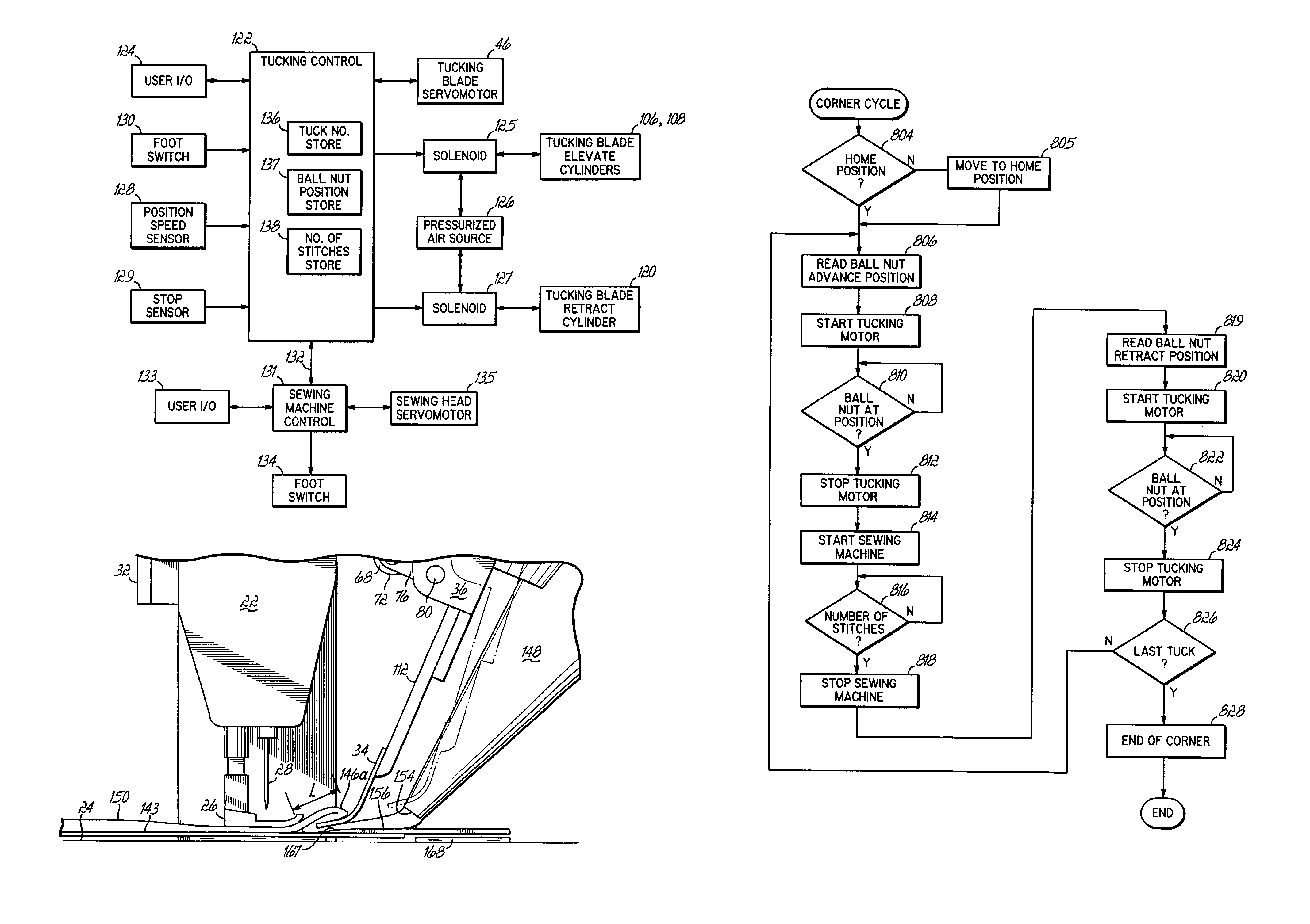
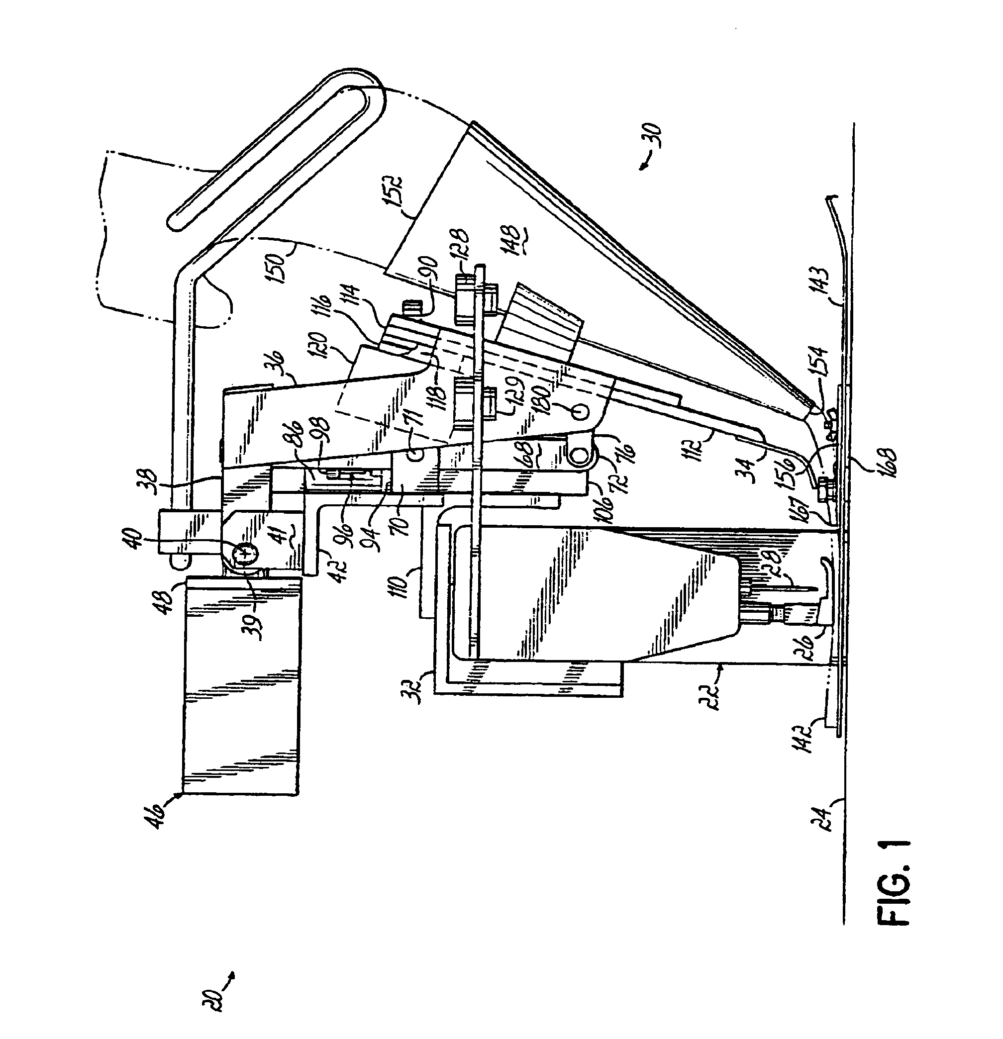
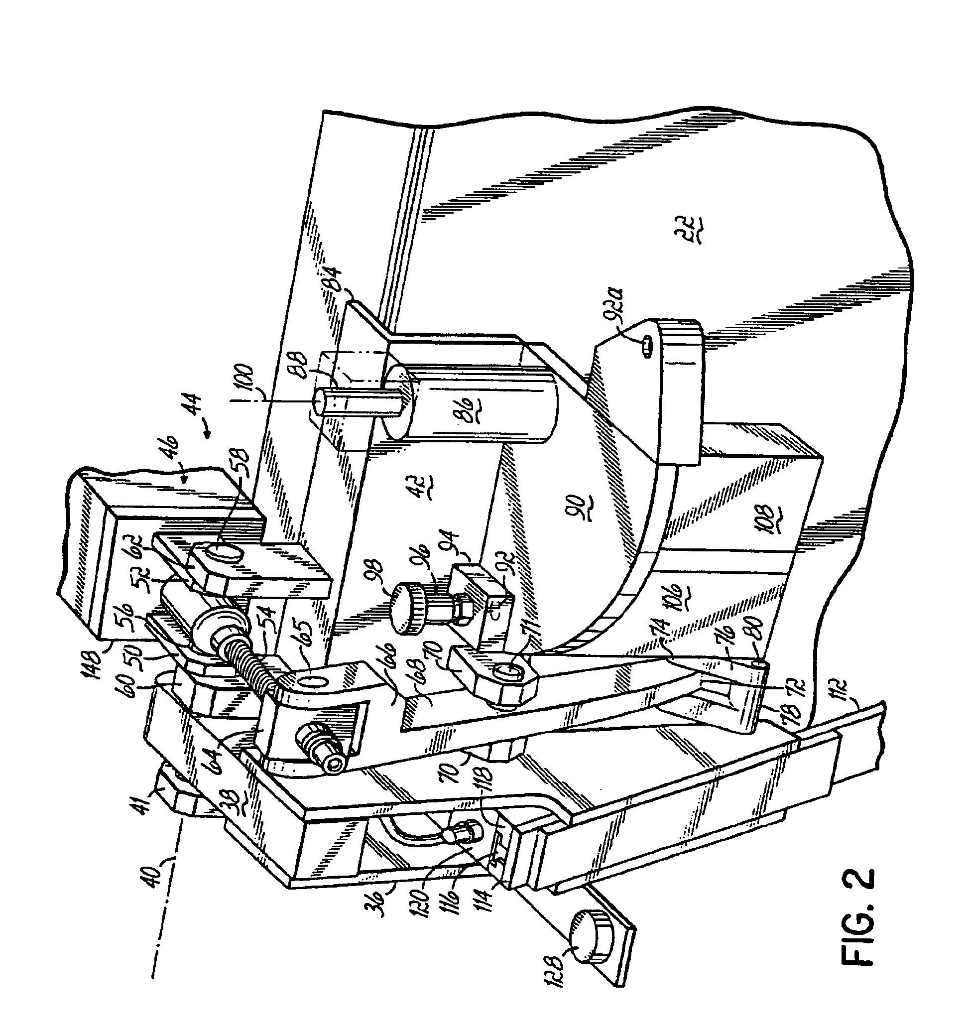
[0026]Referring to FIG. 1, a sewing system 20 has a sewing machine 22 mounted in a base plate 24 in a known manner. The sewing machine includes a presser foot 26 and a needle 28 that is reciprocated and carries a needle thread and a bobbin thread in a known manner. The sewing machine 22 is a commercial sewing machine that performs lock stitching. Lock stitching is a known technique of interlacing a needle thread and bobbin thread, which will not be further described here. A tucking attachment 30 is mounted on the sewing machine by means of mounting brackets 32, 110. The tucking attachment 30 of FIG. 1 includes a tucking blade 34 that is mounted in a tucking arm 36. The tucking arm 36 has an upper end 38 pivotally mounted to a pivot pin or trunnion 39 that is supported between a pair of opposed bearing blocks 41, 60 (FIG. 2) that are mounted on a support bracket 42.

[0027]A tucking blade drive 44 is also mounted to the support bracket 42 and is operative to provide a pivoting motion t...


PUM


Abstract

A tucking attachment for a sewing machine having a tucking blade with one end positioned adjacent material and a tucking blade drive with an output shaft mechanically coupled to the tucking blade. A control, connected to the tucking blade drive, is operable to command the tucking blade drive to move the tucking blade through a programmable displacement to form a tuck in the material adjacent a presser foot of the sewing machine. Thereafter, the sewing machine is operated to sew a number of stitches in the tuck, and the tucking blade is then retracted. Repeating the above cycle of operation permits successive tucks of different lengths to be formed in the material.

Description

FIELD OF THE INVENTION[0001]This invention relates generally to sewing machines and more particularly, to a method and apparatus for tucking fabric in the process of sewing mattresses.BACKGROUND OF THE INVENTION[0002]The sewing of various components of a mattress together to form a finished product presents several sewing challenges. One such challenge is the sewing of the components at their respective corners. For example, pillow-top mattresses are constructed to appear as though a comforter or pillow has been placed on a conventional mattress to provide a more luxurious and comfortable appearance. The pillow-top is connected to the upper decking of the mattress by an intermediate gusset of folded material. Several different techniques are known to sew the edge of the pillow-top corners to corresponding corners of gusset so that the resulting sewn corners have a consistent and pleasing appearance. However, all of those techniques require various manual operations, and therefore, i...

Claims


Application Information

Patent Timeline
IPC IPC(8): D05B35/00D05B35/08D05B11/00
CPCD05B11/005D05B35/085D10B2505/08D05B19/12
Inventor MARCANGELO, STEVEN
Owner L & P PROPERTY MANAGEMENT CO
Why Eureka
Try Eureka