Acoustic element

a technology of acoustic elements and acoustic power, which is applied in the direction of frequency/directions, electrical equipment, engine control, etc., can solve the problems of large sound reproduction and sound strength, and can often become expensive, so as to increase driving ability, reduce turbulence, and achieve maximum sound pressure

Active Publication Date: 2014-01-02
STROMBACK LARS
View PDF8 Cites 16 Cited by
  • Summary
  • Abstract
  • Description
  • Claims
  • Application Information

AI Technical Summary

Benefits of technology

[0005]If more power is desired several rotors according to the invention can be used in parallel alternatively larger rotors may be used. One can also consider to use rotors mounted after each other in order to increase the driving ability, that is the maximally achievable sound pressure. Advantageously one may give the rotors alternating rotation direction and opposed pitch angles in order to decrease turbulence, optimize the airflow and increase efficiency.

Problems solved by technology

Bass loudspeakers must today in order to achieve a good sound reproduction and strength of sound be large and also frequently become expensive.
When the available space is insufficient, as in cars, one simply have to accept that the sound reproduction is afflicted.
In particular there is a great need for small loudspeaker elements for lower frequencies since in many cases large loudspeakers cannot be installed.

Method used


Image

  • Acoustic element
  • Acoustic element
  • Acoustic element

Examples


Embodiment Construction

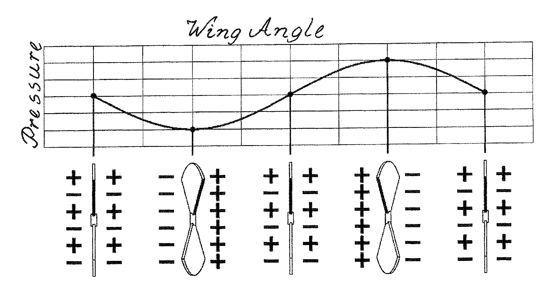
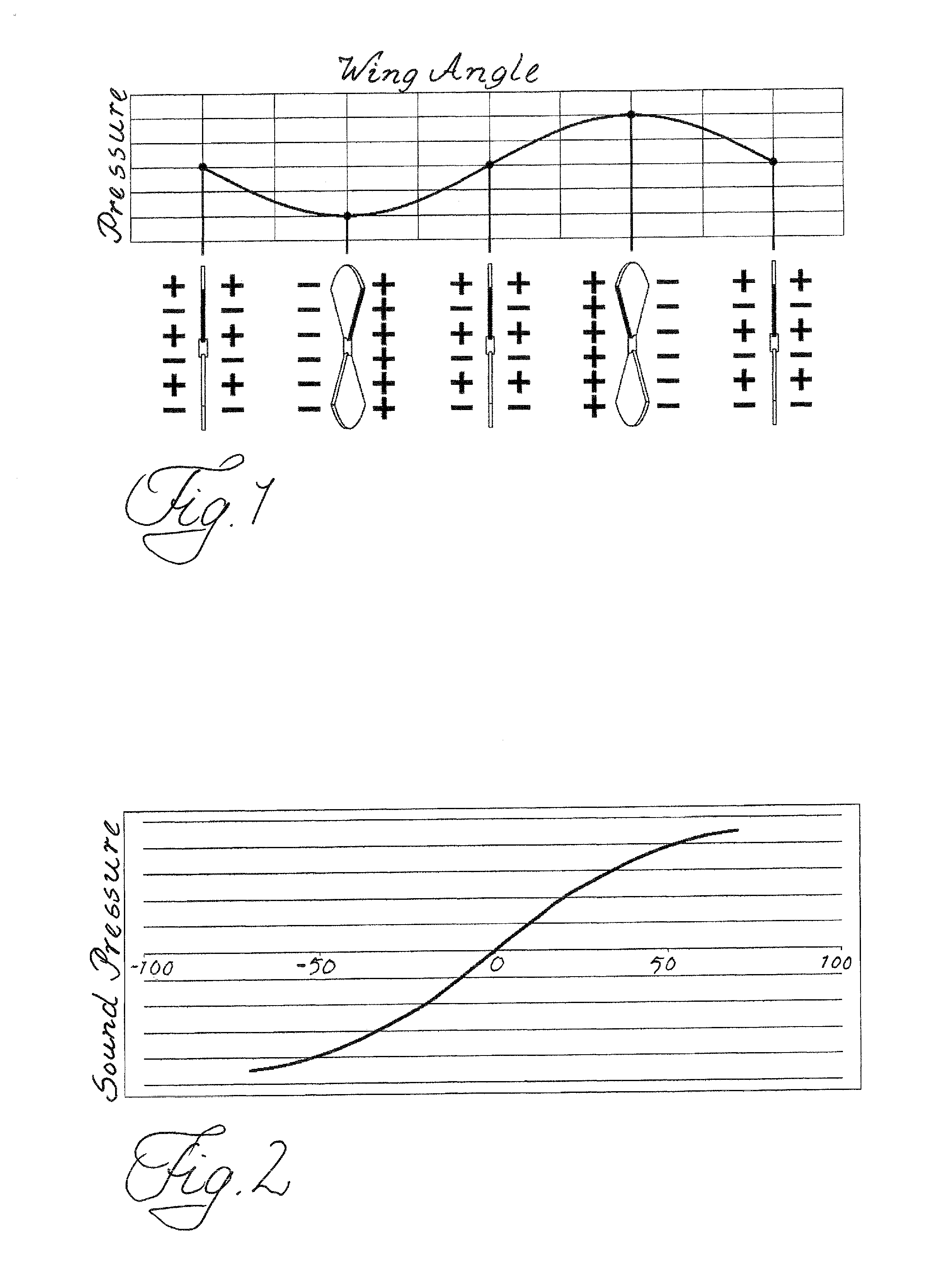
[0029]The element shown in FIG. 5 in accordance with the invention includes a direct driven rotor, that is the rotor is arranged directly on the motor axle of a motor. The rotor has in this example three wings 2, which in their inner ends are pivotable arranged in a hub 3. The wings are pivotable around essentially radial pivot axles 4. The hub 3 is rotated by the motor 1. Each wing in this example has an area corresponding to approximately one third of a circle ring and is in the inner end at a distance from the pivot bearing via an arm 7 connected to a coil axially moveable relative the rotor so that a an axial movement of the coil 5 pivots the wings. The coil 5 is surrounded by a fixed permanent magnet 6 and is fed with electricity against the influence of restraining springs no that it is moved forwards or backwards depending on the direction of electrical current. Advantageously the pivot axles of the wings are situated slightly in front of the pressure center (approximately th...


PUM


Abstract

A combined fan and loudspeaker element, comprising a motor driven rotor provided with wings or blades, wherein the wings or blades are adjustable in pitch resulting together with a rotation of the rotor in an air transport flow, said wings or blades having superimposed thereon a sound-pitch modulation corresponding to a desired sound-pitch with the rotation of the rotor.

Description

CROSS REFERENCE TO RELATED APPLICATION[0001]This application is a continuation-in-part of U.S. patent application Ser. No. 11 / 568,179, filed Oct. 20, 2006, which is a continuation-in-part of PCT International Patent Application Serial No. PCT / SE2005 / 000579 filed 22 Apr. 2005, designating the United States. Priority is also claimed from Swedish Application Serial No. 0401040-1, filed 23 Apr. 2004.BACKGROUND OF THE INVENTION[0002]This invention concerns a combined fan and loudspeaker. Fans and Loudspeakers need space and electric connections. More particularly, the invention concerns acoustic elements, as loudspeakers or microphones in particular for lower frequencies. Bass loudspeakers must today in order to achieve a good sound reproduction and strength of sound be large and also frequently become expensive. When the available space is insufficient, as in cars, one simply have to accept that the sound reproduction is afflicted. In view of the above problem there is a great need for ...

Claims


Application Information

Patent Timeline
Patent Type & Authority Applications(United States)
IPC IPC(8): H04R1/22H04RH04R23/00
CPCH04R1/22H04R23/00F04D29/305F04D33/00F05D2270/62
Inventor STROMBACK, LARS
Owner STROMBACK LARS
Why Eureka
Try Eureka