Labeling area determining apparatus, magnetic resonance apparatus and method for determining tilt of labeling area

a technology of magnetic resonance apparatus and labeling area, which is applied in the direction of diagnostic recording/measuring, measuring using nmr, instruments, etc., can solve the problem of not appropriately determining the labeling area

Active Publication Date: 2014-01-09
GENERAL ELECTRIC CO
View PDF9 Cites 3 Cited by
  • Summary
  • Abstract
  • Description
  • Claims
  • Application Information

AI Technical Summary

Benefits of technology

[0029]According to the above aspects, since the tilt of a labeling area is determined based on the tilt of a head correlated with an area suitable for labeling, the area suitable for the labeling can be determined as a labeling area upon imaging based on an ASL method without depending on the posture of the head.

Problems solved by technology

Therefore, when the labeling area is determined as usual in such a manner that the direction of the normal thereto coincides with the body axial direction of the subject, there is a case where the labeling area is not appropriately determined depending on the posture of the head.

Method used


Image

  • Labeling area determining apparatus, magnetic resonance apparatus and method for determining tilt of labeling area
  • Labeling area determining apparatus, magnetic resonance apparatus and method for determining tilt of labeling area
  • Labeling area determining apparatus, magnetic resonance apparatus and method for determining tilt of labeling area

Examples


Embodiment Construction

[0044]An exemplary embodiment will hereinafter be described in detail with reference to the accompanying drawings. Incidentally, the disclosure is not limited to or by the exemplary embodiment.

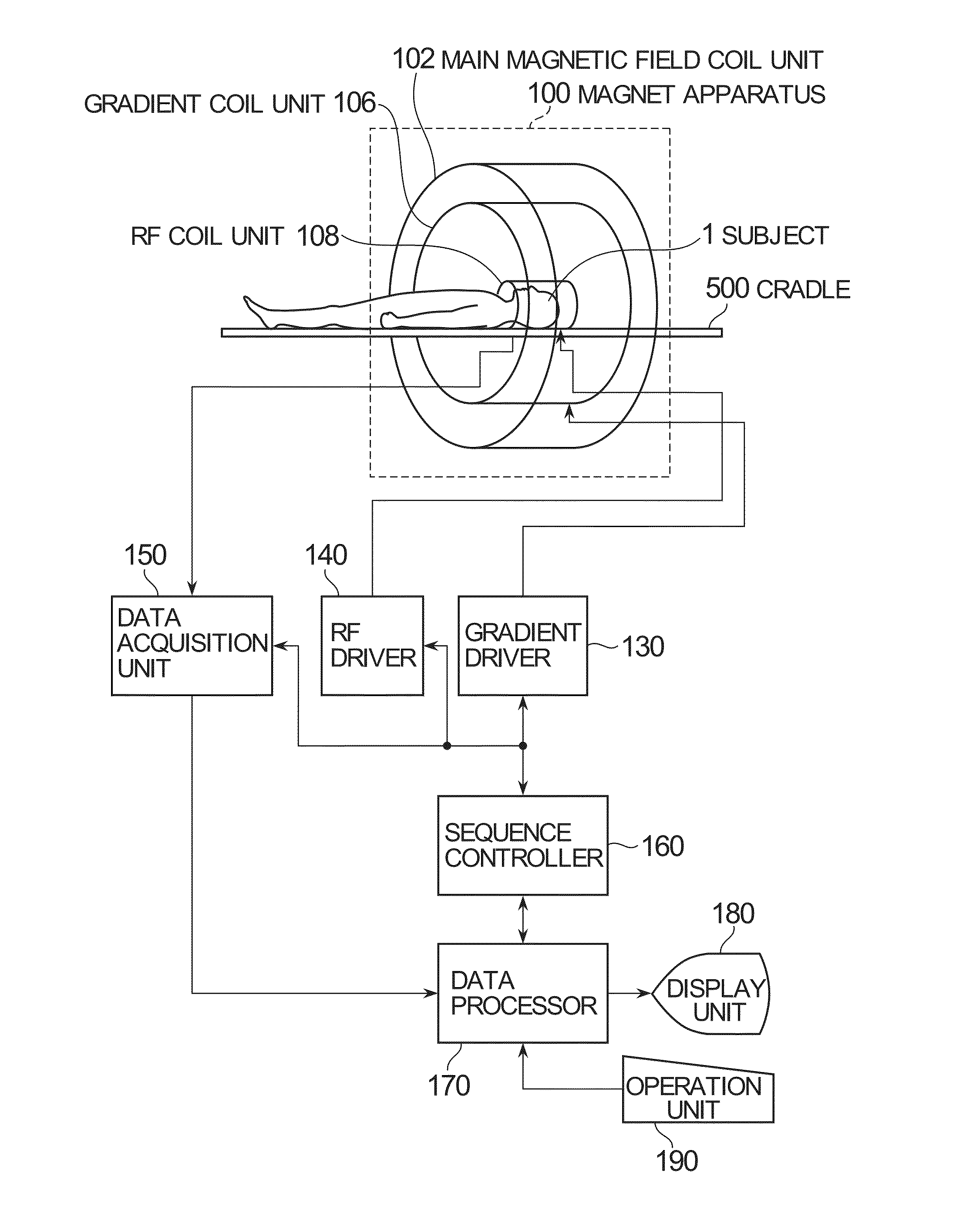
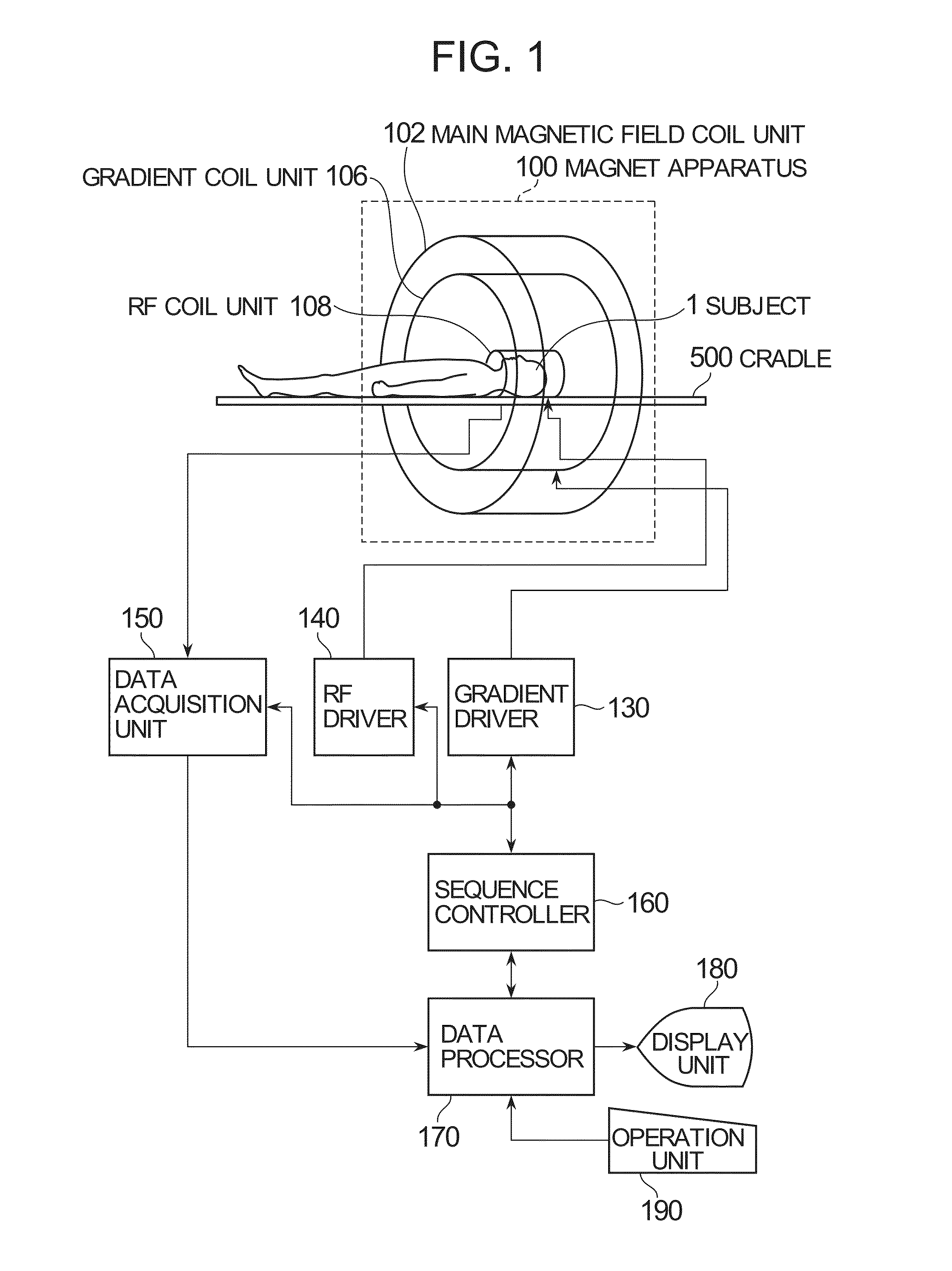
[0045]A block diagram of a magnetic resonance imaging apparatus is shown in FIG. 1. As shown in the same drawing, the magnetic resonance imaging apparatus has a magnet apparatus 100. The magnet apparatus 100 has a main magnetic field coil unit 102, a gradient coil unit 106 and an RF (Radio Frequency) coil unit 108. These coil units have an approximately cylindrical shape respectively and disposed concentrically with each other. A subject 1 to be imaged is placed on a cradle 500 so as to be carried in an approximately columnar internal space (bore) of the magnet apparatus 100 and carried out therefrom by an unillustrated conveying means. The head of the subject 1 is accommodated within the RF coil unit 108.

[0046]The main magnetic field coil unit 102 forms a static magnetic field within the inte...


PUM


Abstract

A labeling area determining apparatus is provided. The labeling area determining apparatus includes a detecting device configured to detect a tilt of a head relative to a body axial direction of a subject to be imaged by an arterial spin labeling method, and a determining device configured to determine a tilt of a labeling area of spins relative to the body axial direction of the subject, based on the tilt of the head detected by the detecting device.

Description

CROSS REFERENCE TO RELATED APPLICATIONS[0001]This application claims the benefit of Japanese Patent Application No. 2012-151947 filed Jul. 6, 2012, which is hereby incorporated by reference in its entirety.BACKGROUND OF THE INVENTION[0002]The present invention relates to a labeling area determining apparatus and a magnetic resonance apparatus which determine a labeling area in an ASL (Arterial Spin Labeling) imaging method, and a program therefor.[0003]In a magnetic resonance imaging (MRI) apparatus, a subject to be imaged is carried in an internal bore of a magnet apparatus, i.e., an imaging space with a static magnetic field formed therein. A gradient magnetic field and an RF (Radio Frequency) magnetic field are applied thereto to excite spins in the subject and thereby generate magnetic resonance signals, whereby an image is reconstructed based on the received signals from the magnetic resonance signals.[0004]Using such an MRI apparatus, there has been known perfusion imaging by ...

Claims


Application Information

Patent Timeline
Patent Type & Authority Applications(United States)
IPC IPC(8): G01R33/56
CPCG01R33/56G01R33/5616G01R33/56366A61B5/055
Inventor IKEZAKI, YOSHIKAZUUNO, MARIE
Owner GENERAL ELECTRIC CO
Why Eureka
Try Eureka