Recording apparatus
a recording apparatus and recording technology, applied in printing and other directions, can solve the problems of erroneous mounting of ink cartridges on a different position, inability to mount, and inability to achieve mounting,
- Summary
- Abstract
- Description
- Claims
- Application Information
AI Technical Summary
Benefits of technology
Problems solved by technology
Method used
Image

Examples
second embodiment
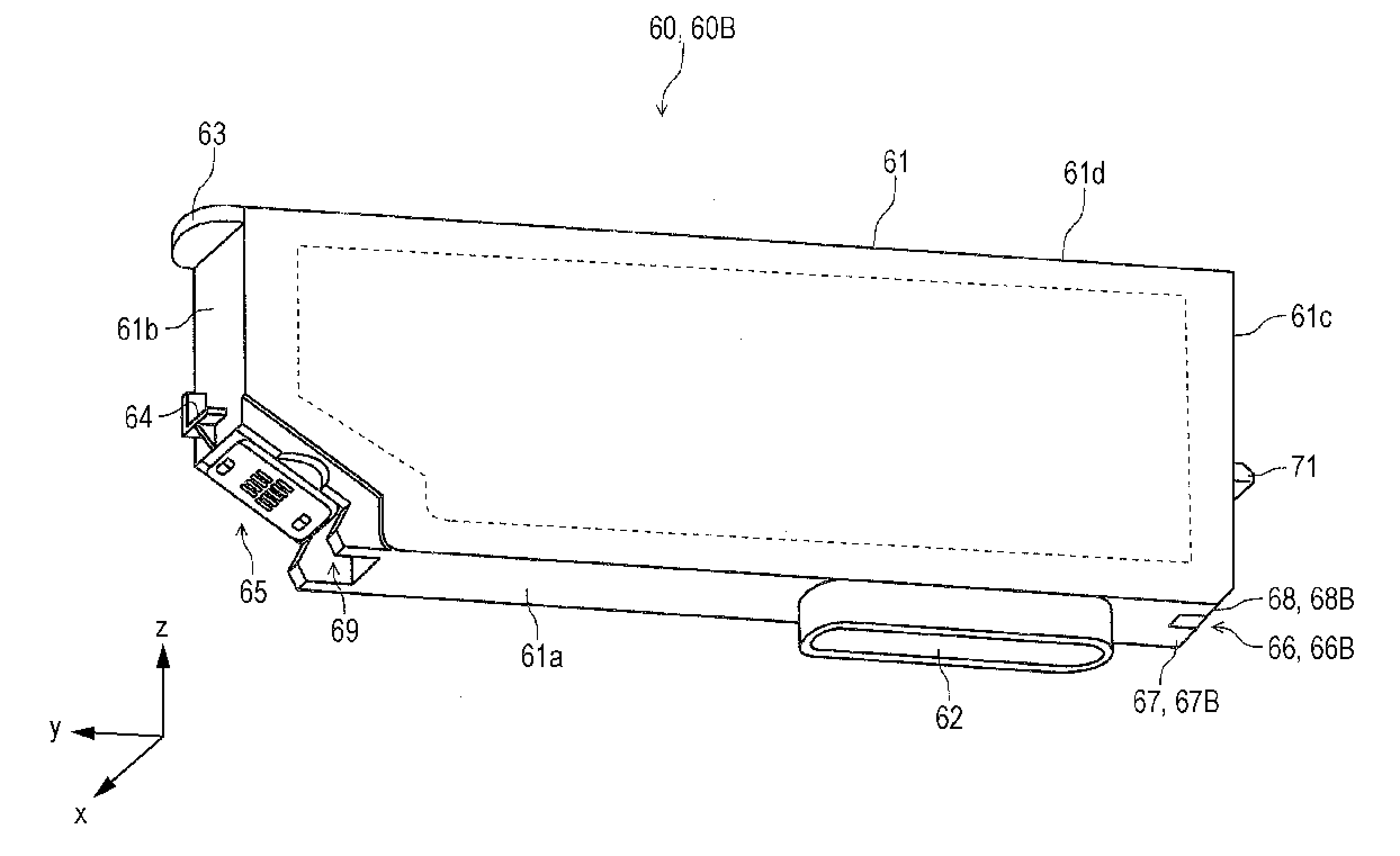
[0098]FIG. 11 to FIG. 13 are drawings illustrating an ink cartridge 60S according to the FIG. 11 is a plan view of the ink cartridge 60S viewed from a +x direction toward a −x direction. In other words, it is a drawing illustrating a side surface (right side surface) 61e on the +x side of the ink cartridge 60S. FIG. 12 is a plan view of the ink cartridge 60S viewed from the −x direction toward the +x direction. In other words, it is a drawing illustrating a side surface (left side surface) 61f on the −x side of the ink cartridge 60S. FIG. 13 is a perspective view of the ink cartridge 60S.
first embodiment
[0099]A first different point from the ink cartridge 60 illustrated in FIG. 7 is that an indentation 80 which receives at least part of the partitioning panel 44 (see FIG. 5, FIG. 6, and FIG. 8) is provided on the right side surface. An inner edge 82 of the indentation 80 on the −y side functions as a guide which guides an ink cartridge 61A to the mounted posture smoothly by coming into abutment with an upper edge of the partitioning panel 44 when the ink cartridge 60S is mounted in the ink cartridge mounting chamber 29a.
[0100]In a state in which the ink cartridge 60S is mounted in the ink cartridge mounting chamber 29a, an upper portion of the partitioning panel 44 is accommodated in the indentation 80. With the provision of the indentation 80, the ink cartridges 60S may be arranged in the ink cartridge mounting chamber 29a without forming gaps therebetween. Accordingly, the maximum amount of storage of ink in the ink cartridge 60S may be secured and increase in size of the carri...
third embodiment
[0102]FIG. 14 to FIG. 16 are drawings illustrating an ink cartridge 60M according to the FIG. 14 is a plan view of the ink cartridge 60M viewed from the +x direction toward the −x direction. In other words, it is a drawing illustrating the side surface (right side surface) 61e on the side of the +x direction of the ink cartridge 60M. FIG. 15 is a plan view of the ink cartridge 60M viewed from the −x direction toward the +x direction. In other words, it is a drawing illustrating the side surface (left side surface) 61f on the −x side of the ink cartridge 60M. FIG. 16 is a perspective view of the ink cartridge 60M.
[0103]Different points among the ink cartridge 60M according to the third embodiment, the ink cartridge 60 according to the first embodiment illustrated in FIG. 7, and the ink cartridge 60S according to the second embodiment illustrated in FIG. 11 to FIG. 13 are as follows.
[0104]The ink cartridge 60M has a width which corresponds to approximately the sum of the widths of th...
PUM
 Abstract
Description
Claims
Application Information
 - R&D
- Intellectual Property
- Life Sciences
- Materials
- Tech Scout
- Unparalleled Data Quality
- Higher Quality Content
- 60% Fewer Hallucinations
Browse by: Latest US Patents, China's latest patents, Technical Efficacy Thesaurus, Application Domain, Technology Topic, Popular Technical Reports.
© 2025 PatSnap. All rights reserved.Legal|Privacy policy|Modern Slavery Act Transparency Statement|Sitemap|About US| Contact US: help@patsnap.com