Vehicle Seat

a technology for vehicles and seats, applied in the field of vehicles seats, can solve problems such as the bulkyness of the mechanism, and achieve the effects of reducing the motion sickness of the occupant, reducing the occupant's motion sickness, and being more stabl

Pending Publication Date: 2021-10-28
TS TECH CO LTD
View PDF0 Cites 1 Cited by
  • Summary
  • Abstract
  • Description
  • Claims
  • Application Information

AI Technical Summary

Benefits of technology

[0081]According to one aspect of the present invention, a vehicle seat configured to be install in a vehicle comprises: a seat cushion; a seat back provided at a rear portion of the seat cushion; a headrest including a main part connected to an upper end of the seat back to support a back of a head of an occupant, a left side part connected to a left edge of the main part to be rotatable about a vertical axis, a right side part connected to a right edge of the main part to be rotatable about a vertical axis, a left drive device for rotating the left side part forward relative to the main part; and a right drive device for rotating the right side part forward relative to the main part; an acceleration acquisition device configured to acquire an acceleration applied in a lateral direction; and a control device which, when a rightward acceleration is acquired by the acceleration acquisition device, makes the right drive device rotate the right side part forward until the right side part is positioned on a right side of the head of the occupant, and when a leftward acceleration is acquired by the acceleration acquisition device, makes the left drive device rotate the left side part forward until the left side part is positioned on a left side of the head of the occupant. According to this configuration, when an acceleration is applied to the occupant rightward, the right side part is rotated until it is positioned to the right of the head of the occupant. Thereby, the rightward movement of the head of the occupant due to centrifugal force is restricted by the right side part. When an acceleration is applied to the occupant leftward, the left side part is rotated until it is positioned to the left of the head of the occupant. Thereby, the leftward movement of the head of the occupant due to centrifugal force is restricted by the left side part. In this way, the movement of the head of the occupant is restricted, so that the posture of the head of the occupant is controlled. Thereby, the posture of the head of the occupant is stabilized and motion sickness of the occupant can be reduced.
[0082]According to the configuration where, in the above aspect, the right side part has a right contact surface that opposes the head of the occupant when the right side part is rotated forward, the left side part has a left contact surface that opposes the head of the occupant when the left side part is rotated forward, and the control device rotates the right side part until the right contact surface contacts a right side surface of the head when a rightward acceleration is acquired by the acceleration acquisition device and rotates the left side part until the left contact surface contacts a left side surface of the head when a leftward acceleration is acquired by the acceleration acquisition device, when an acceleration is applied to the occupant rightward, the right side part contacts the right side surface of the head with the right contact surface thereof and supports the head of the occupant from the right side. Similarly, when an acceleration is applied to the occupant leftward, the left side part contacts the left side surface of the head with the left contact surface thereof and supports the head of the occupant from the left side. In this way, when an acceleration is applied to the occupant in the lateral direction, the right side part and the left side part support the head of the occupant with the respective contact surfaces, whereby the posture of the head of the occupant is more stabilized.
[0083]According to the configuration where, in the above aspect, the right contact surface and the left contact surface are provided with respective light emitting devices, each light emitting device includes multiple light emitting elements arranged substantially horizontally, the light emitting device provided on the right side part emits light to correspond to optical flow of a view from a right side window of the vehicle when the right side part is positioned on the right side of the head, and the light emitting device provided on the left side part emits light to correspond to optical flow of a view from a left side window of the vehicle when the left side part is positioned on the left side of the head, when an acceleration is applied in the lateral direction, the light emitting device that emits light to correspond to the optical flow of the view from the side window is disposed to the side of the occupant. Thereby, the occupant can acquire information related to the acceleration of the vehicle through vision. As a result, the difference between the acceleration detected by the vestibular system in the ear and the visually perceived acceleration becomes small, whereby motion sickness of the occupant can be reduced.
[0084]According to the configuration where, in the above aspect, the right contact surface and the left contact surface are provided with respective displays, the display of the right side part displays optical flow of a view from a side window of the vehicle when the right side part is positioned on the right side of the head, and the display of the left side part displays optical flow of a view from a side window of the vehicle when the left side part is positioned on the left side of the head, the occupant can visually acquire the information related to the acceleration of the vehicle. Thereby, the difference between the acceleration detected by the vestibular system and the visually perceived acceleration becomes small, whereby motion sickness of the occupant can be reduced.
[0085]According to the configuration where, in the above aspect, the acceleration acquisition device is an acceleration sensor supported by one of the seat cushion, the seat back, and the headrest, the acceleration applied to the body of the occupant can be acquired more accurately and in a simple manner.
[0086]According to the configuration where, in the above aspect, a car navigation system capable of acquiring map information and a position of the vehicle is installed in the vehicle, and the acceleration acquisition device is configured to receive the map information and the position of the vehicle from the car navigation system and to calculate the acceleration, the acceleration applied to the occupant can be predicted based on the map information and the position of the vehicle, and the left side part and the right side part can be displaced based on the predicted acceleration. This makes it possible to displace the left side part and the right side part in accordance with the instant at which the centrifugal force is applied and thereby to restrict the movement of the head of the occupant more reliably. Therefore, motion sickness of the occupant can be reduced.

Problems solved by technology

On the other hand, in the vehicle seats of Patent Document 1 and Patent Document 2, since the movement or tilt of the upper body of the occupant is controlled, there is a problem that the mechanism becomes bulky.

Method used


Image

  • Vehicle Seat
  • Vehicle Seat
  • Vehicle Seat

Examples


first embodiment

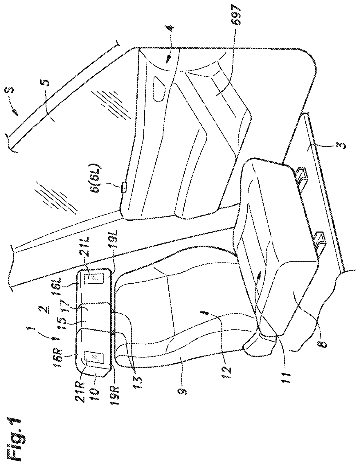
[0156]As shown in FIG. 1, a vehicle seat 1 is installed in a vehicle S such as an automobile. The vehicle seat 1 is disposed on a floor 3 defining a bottom portion of a cabin 2 at a position adjacent to the driver's seat to constitute a front passenger seat (assistant seat). On an outboard side of each of the driver's seat and the front passenger seat, a door 4 is provided to allow an occupant to get in and out of the vehicle S. The doors are provided with respective side windows 5 for allowing the occupant to have views on the left and right sides of the vehicle S and respective camera 6s for successively acquiring images on the left and right outer sides of the vehicle S through the side windows 5 in every prescribed time period. In the following, the fore and aft, lateral, and vertical directions are defined using the fore and aft direction of the vehicle S as a reference. Also, the camera provided on the left door 4 of the vehicle S will be referred to as the left camera 6L and ...

second embodiment

[0182]As shown in FIG. 6 and FIG. 7, a vehicle seat 41 according to the second embodiment differs from the first embodiment only in that a left light emitting device 43L is provided in place of the left display 21L, a right light emitting device 43R is provided in place of the right display 21R, and steps ST6, ST7, ST9, and ST10 of the motion sickness prevention process are modified. The other configuration is the same as in the first embodiment, and the description thereof will be omitted.

[0183]The right light emitting device 43R includes multiple LED elements 44L (light emitting elements) arranged substantially horizontally along the right contact surface 19R. The left light emitting device 43L includes multiple LED elements 44R (light emitting elements) arranged in the vehicle width direction along the left contact surface 19L. The right light emitting device 43R and the left light emitting device 43L are each connected to the control device 23. The control device 23 can control ...

third embodiment

[0189]As shown in FIG. 8, a vehicle seat 51 according to the third embodiment is installed in a vehicle 53 provided with a car navigation system 52. The car navigation system 52 is configured to be capable of acquiring the map information and the position of the vehicle 53 via GPS, the Internet, or the like. The vehicle seat 51 according to the fourth embodiment is not provided with the acceleration sensor 22, and instead is provided in the control device 23 with an acceleration acquisition device 54 which receives the map information and the position of the vehicle 53 from the car navigation system 52 and calculates a lateral direction acceleration applied to the vehicle 53. The other configuration of the vehicle seat 51 according to the fourth embodiment is the same as in the first embodiment, and therefore, the description thereof will be omitted.

[0190]The acceleration acquisition device 54 is configured as software stored in the memory of the control device 23 and executed by th...


PUM


Abstract

To provide a vehicle seat in which the posture of the head of the occupant is controlled with a simpler configuration to reduce motion sickness of the occupant, the vehicle seat includes: a seat cushion; a seat back; a headrest including a main part configured to support the back of the head of the occupant, a left side part connected to a left edge of the main part to be rotatable about a vertical axis, a right side part connected to a right edge of the main part to be rotatable about a vertical axis, a left drive device for rotating the left side part forward relative to the main part, and a right drive device for rotating the right side part forward relative to the main part; an acceleration acquisition device; and a control device which, when a rightward acceleration is acquired by the acceleration acquisition device, makes the right drive device rotate the right side part forward until the right side part is positioned on a right side of the head of the occupant, and when a leftward acceleration is acquired by the acceleration acquisition device, makes the left drive device rotate the left side part forward until the left side part is positioned on a left side of the head of the occupant.

Description

CROSS REFERENCE TO RELATED APPLICATIONS[0001]This application is the U.S. National Stage entry of International Application No. PCT / JP2019 / 039158 filed under the Patent Cooperation Treaty having a filing date of Oct. 3, 2019, which claims priority to Japanese Patent Application No. 2018-190786 having a filing date of Oct. 9, 2018, Japanese Patent Application No. 2018-231097 having a filing date of Dec. 10, 2018, and Japanese Patent Application No. 2018-230762 having a filing date of Dec. 10, 2018, all of which are incorporated herein by reference.TECHNICAL FIELD[0002]The present invention relates to a vehicle seat for preventing motion sickness of an occupant.BACKGROUND ART[0003]A vehicle seat capable of preventing rolling of an upper body of an occupant is known (for example, Patent Document 1). In the vehicle seat of Patent Document 1, an upper portion of a seat back is configured to have a higher support resistance against lateral movement of the upper body of the occupant than a...

Claims


Application Information

Patent Timeline
Patent Type & Authority Applications(United States)
IPC IPC(8): B60N2/885B60N2/75B60N2/853B60N2/879
CPCB60N2/885B60N2/879B60N2/853B60N2/79B60N2/0268B60N2/02246
Inventor SAKOTA, MASAHIROITO, TAKAYOSHIKOWATA, KOHEITANABE, JINICHI
Owner TS TECH CO LTD
Why Eureka
Try Eureka