Insertion system for electrical conductor

a technology of insertion system and electrical conductor, which is applied in the direction of manufacturing tools, metal working apparatus, and stator/rotor body, etc., can solve the problems of increasing cost, complicated devices, and the possibility of widening the gap between the insulating paper and the structure of the opening fixture, and achieves the effect of reliable widening of the gap, simple configuration and low cos

Active Publication Date: 2014-01-16
HONDA MOTOR CO LTD
View PDF11 Cites 17 Cited by
  • Summary
  • Abstract
  • Description
  • Claims
  • Application Information

AI Technical Summary

Benefits of technology

[0020]In addition, the present invention provides the guide part in an annular shape, as well as multiply partitioning the guide part in the circumferential direction. Moreover, the second moving part is provided that causes each of the partitioned guide parts to move in the radial direction. It is thereby possible to cause the guide parts to move outwards in the radial direction after the ...

Problems solved by technology

However, with the insertion system of Patent Document 1, so long as the gap between insulating paper is of an extent slightly narrower than usual, it is possible to widen the gap between the insulating paper by the opening fixture; however, in a case of the gap between insulating paper being narrower ...

Method used


Image

  • Insertion system for electrical conductor
  • Insertion system for electrical conductor
  • Insertion system for electrical conductor

Examples


Embodiment Construction

[0035]Hereinafter, an embodiment of the present invention will be explained in detail while referencing the drawings.

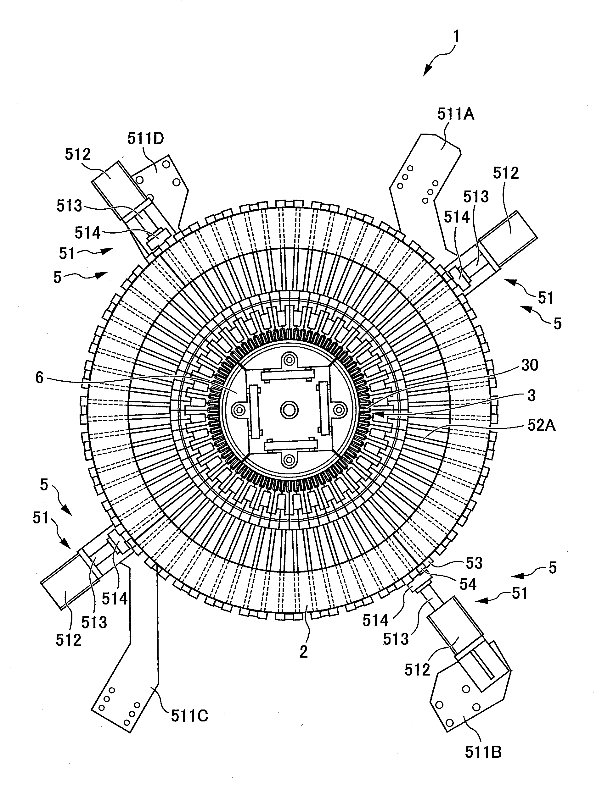
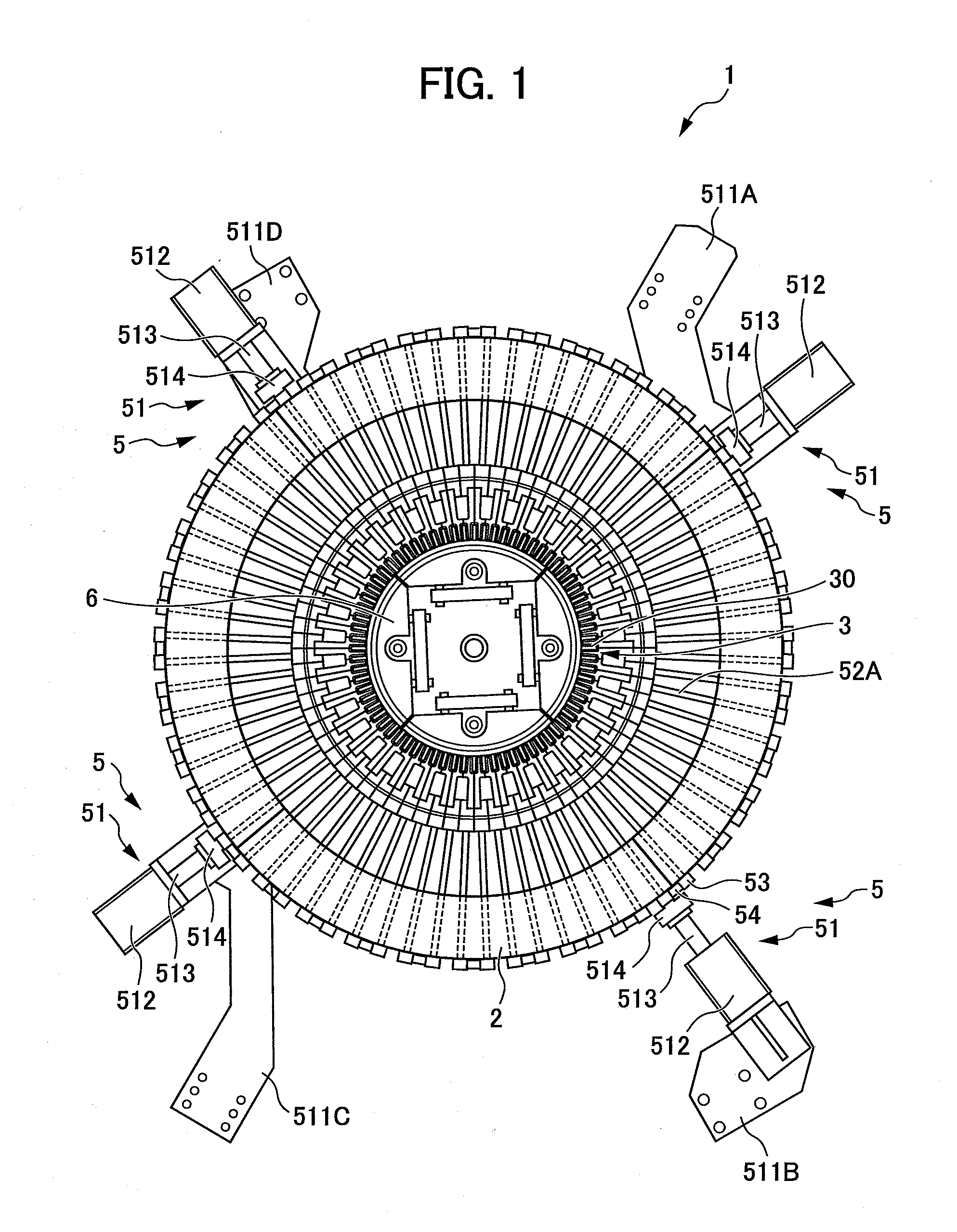
[0036]An insertion system 1 according to the present embodiment inserts a substantially U-shaped electrical conductor into slots of a stator core in which insulating paper has been arranged. As the electrical conductor, one can be used in which a plurality of substantially U-shaped coil elements for rotary electric machines is aligned in an annular shape while overlapping in the circumferential direction.

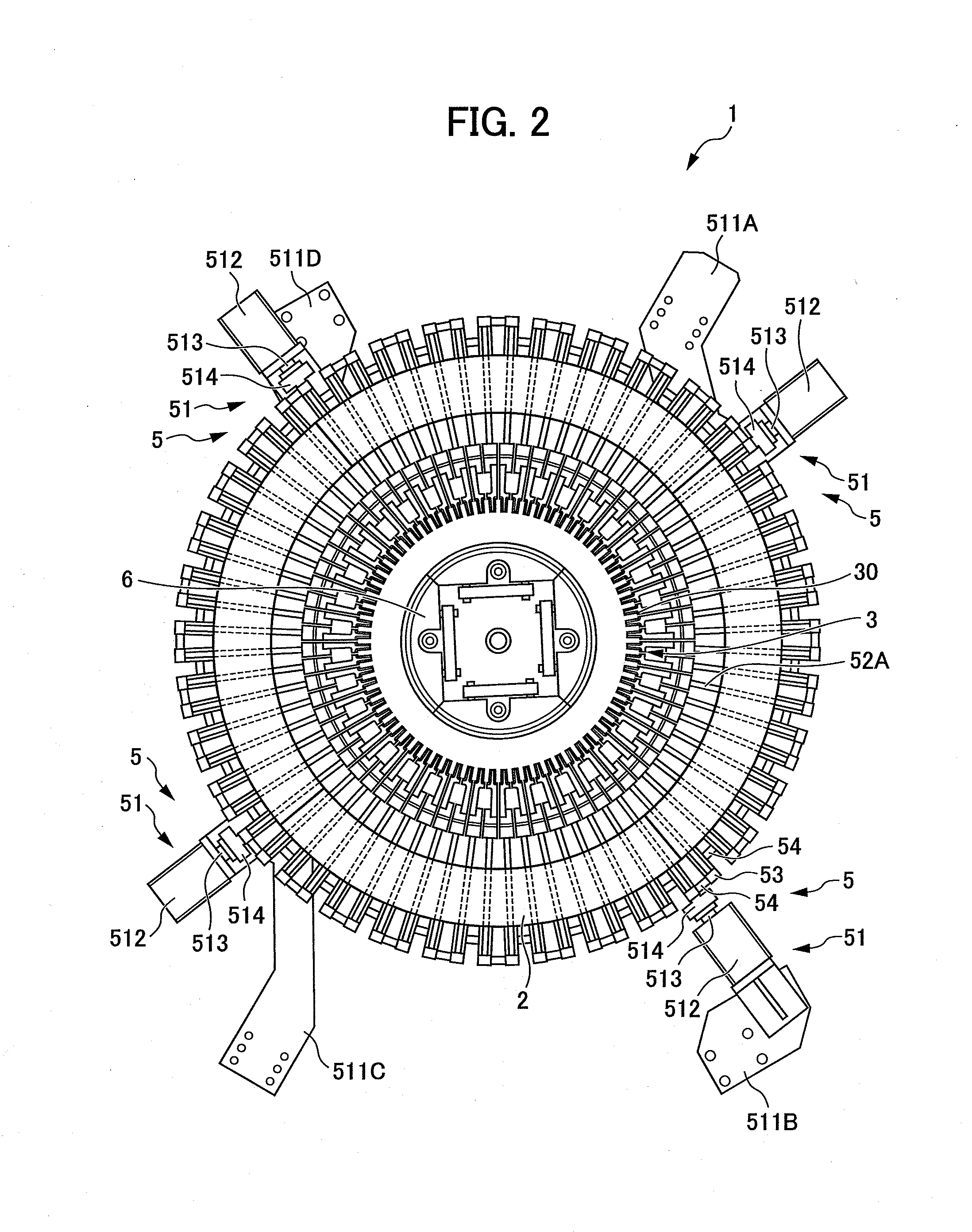
[0037]FIGS. 1 and 2 are plan views of the insertion system 1 according to one embodiment of the present invention. In more detail, FIG. 1 is a view showing a state in which guide parts described later have advanced to gather at the inside in the radial direction, and FIG. 2 is a view showing a state in which the guide parts have retracted to scatter to the outside in the radial direction. In addition, FIG. 3 is a side view of the insertion system 1. It should be noted...


PUM


Abstract

An insertion system for electrical conductors is provided that can widen the gap between insulating paper. An insertion system (1) includes: a first moving part (4) that causes a leg of the coil element (10) to move in an insertion direction of a slot (16); a guide part (3) that guides the leg into the slot (16); and a pair of first spreader plates (7A) and a pair of second spreader plates (7B) that can spread at a leading end side thereof, in which these pairs of spreader plates are formed so as to extend inclined relative to the insertion direction so as to approach each other towards a leading end side, and a gap therebetween is narrower than a width of insulating paper (17) at the leading end side, and is wider than a width of the leg of the coil element (10) at a base end side.

Description

[0001]This application is based on and claims the benefit of priority from Japanese Patent Application No. 2012-156724, filed on 12 Jul. 2012, the content of which is incorporated herein by reference.BACKGROUND OF THE INVENTION[0002]1. Field of the Invention[0003]The present invention relates to an insertion system for electrical conductors. In detail, it relates to an insertion system that inserts electrical conductors into the slots of a stator core.[0004]2. Related Art[0005]Conventionally, the stator coil of a rotary electric machine is formed by the legs of each substantially U-shaped electrical conductor being inserted into respective slots of a stator core from a central axial direction, and then the ends of each leg being connected together. Insulating paper is inserted inside each substantially rectangular slot so as to cover the all sides thereof, and contact between the electrical conductor and stator core is avoided by way of this insulating paper.[0006]Usually, insulatin...

Claims


Application Information

Patent Timeline
IPC IPC(8): H02K15/02
CPCH02K15/024H02K15/064Y10T29/53143Y10T29/5313Y10T29/49071Y10T29/532Y10T29/53078Y10T29/49073H02K15/085H02K15/067
Inventor YOSHIDA, TORUYAMADA, MITSUHIROMATSUMOTO, YUTAKAOHNO, KENICHIHIRAGA, KAZUHITONAKAJIMA, JUNJI
Owner HONDA MOTOR CO LTD
Why Eureka
Try Eureka