Locking pin assembly

a technology of locking pins and assembly parts, which is applied in the direction of construction, key-type connections, fastening means, etc., can solve the problems of high degree of wear in the working environment of excavators and excavators, installation of teeth, and potential accidental injuries

Inactive Publication Date: 2014-01-16
CUI KAN
View PDF5 Cites 17 Cited by
  • Summary
  • Abstract
  • Description
  • Claims
  • Application Information

AI Technical Summary

Benefits of technology

[0008]These and other features of the present invention will become readil

Problems solved by technology

Excavators and excavating machines experience a high degree of wear in the working environment.
This type of system can be a dangerous manner of installing the teeth, which can lead to potential accidental injuries.
While this is a fu

Method used


Image

  • Locking pin assembly
  • Locking pin assembly
  • Locking pin assembly

Examples


Embodiment Construction

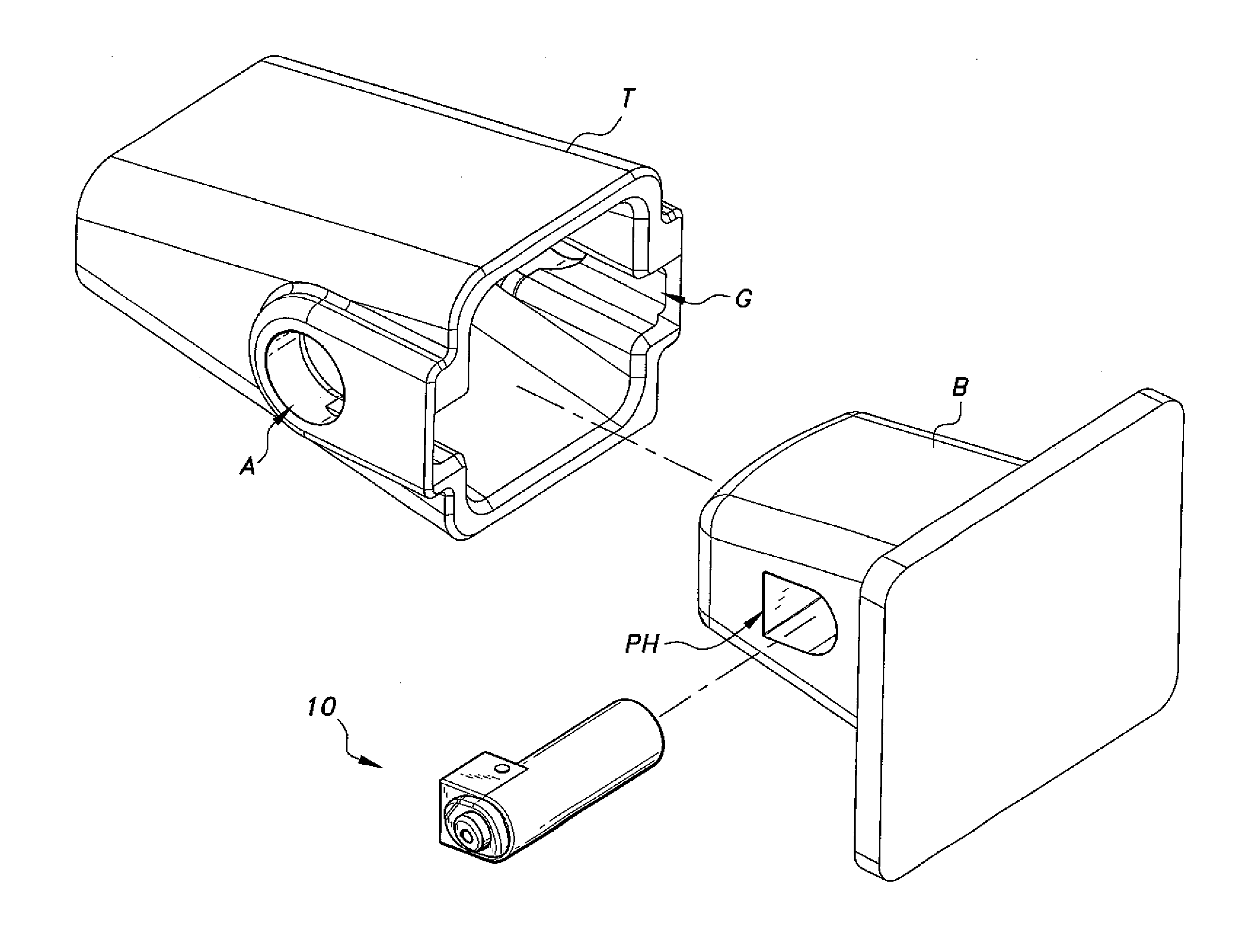
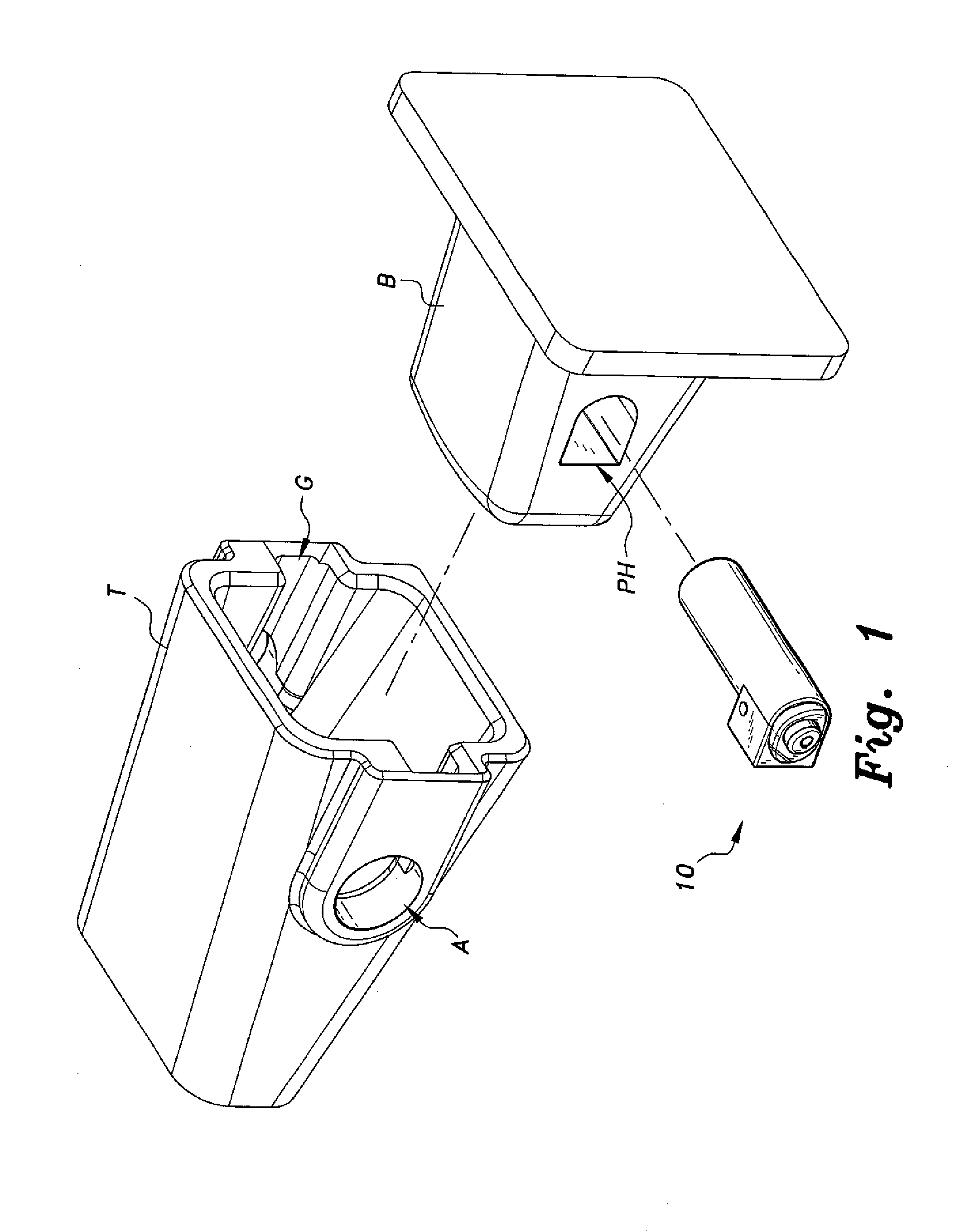
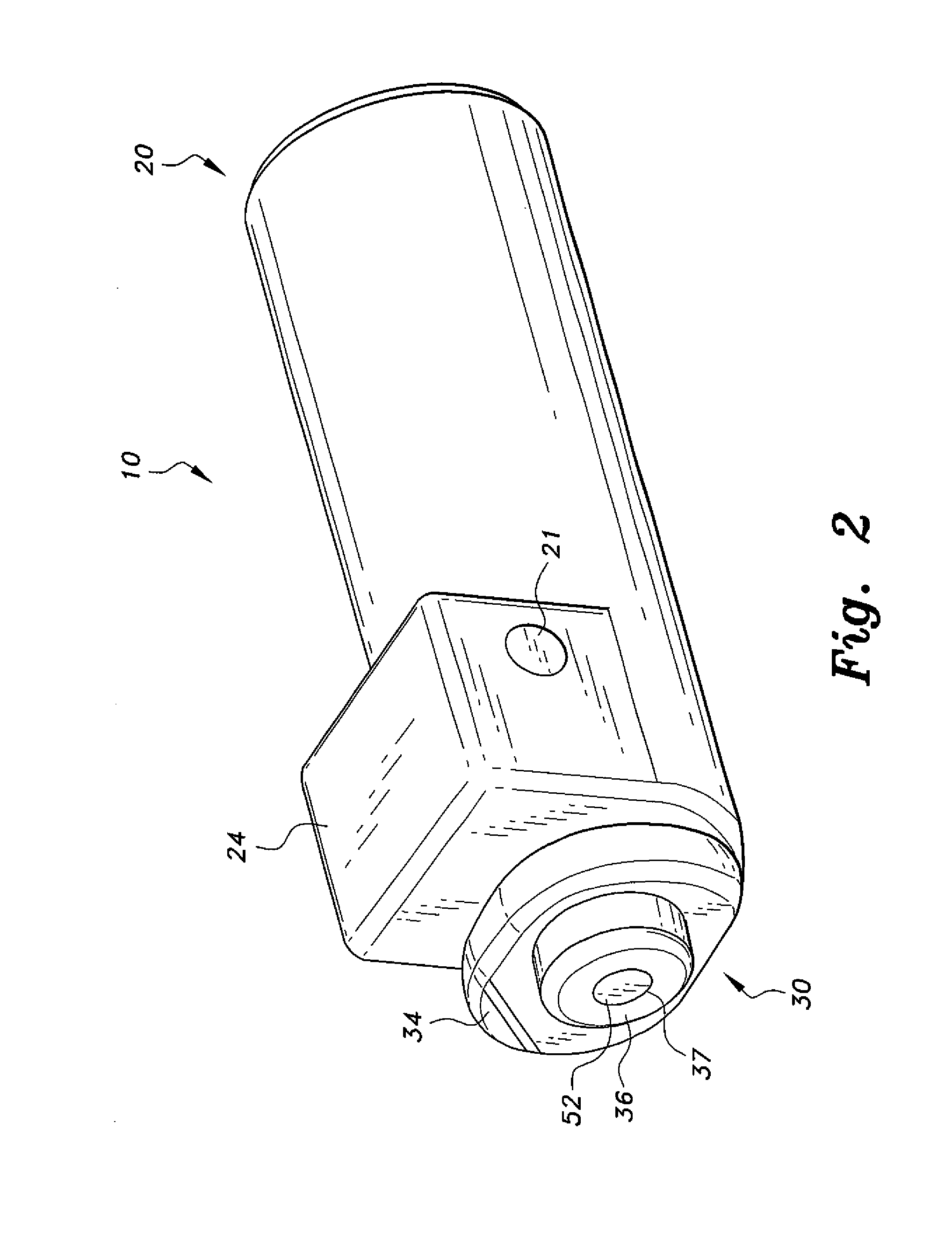
[0021]The locking pin assembly, a first embodiment of which is generally referred to by the reference number 10 in the drawings, provides safe and easy locking and unlocking features that requires minimal physical effort. The pin assembly 10, shown in FIGS. 1-4, includes a pin housing 20 (also referred to as a pin body or cartridge) and a pin mechanism or component 30 selectively inserted into the pin housing 20. The pin housing 20 is an elongate, substantially hollow cylindrical housing having a partially squared section 24 attached to the cylinder at one end. This partially squared section 24 results in a U-shaped or horseshoe shaped periphery at one end of the housing 20. The pin housing 20 is configured for insertion into a correspondingly shaped bore PH formed in the tooth base B. The pin housing 20 protects the pin mechanism 30 and prevents the housing 20 from rotating relative to the tooth base B. In order to prevent such rotation, it is preferable that the bore PH and the pi...


PUM


Abstract

The locking pin assembly includes an elongate pin housing and a pin mechanism insertably mounted into a bore in the pin housing. The pin mechanism includes at least one rotator section integral with a pin shaft. A rotation-locking member is integrally attached to the bottom of the pin shaft, the locking member having a non-circular shape. An elongate post having a rotation-locking collar attached to one end of the post is slidable in a keyhole extending through the pin. A non-circular recess is formed in the rotation-locking collar, which selectively receives the locking member therein. A spring is disposed behind the rotation-locking collar. The spring normally biases the locking collar into engagement with the locking member. A key is provided to axially push the post to selectively disengage the locking member for selective rotation of the rotator section between locked and unlocked positions.

Description

CROSS-REFERENCE TO RELATED APPLICATION[0001]This application claims the benefit of U.S. Provisional Patent Application Ser. No. 61 / 670,977, filed Jul. 12, 2012.1. FIELD OF THE INVENTION[0002]The present invention relates to locking devices, and particularly to a locking pin assembly for selectively locking mating parts in general, and in particular, for replacing excavating teeth with ease and without the use of impact tools.2. DESCRIPTION OF THE RELATED ART[0003]Many interlocking structures require some sort of locking mechanism connecting the parts together. Some examples include extendable legs on load bearing structures, articulating beams and the means for setting angular positions of the beams, parts for connecting to a stand and the like. One area in which locking mechanisms are used is for securing replaceable or interchangeable elements, such as the teeth on excavators. Excavators and excavating machines experience a high degree of wear in the working environment. The teeth...

Claims


Application Information

Patent Timeline
IPC IPC(8): E02F9/28
CPCE02F9/2833E02F9/2841F16B3/00
Inventor CUI, KAN
Owner CUI KAN
Why Eureka
Try Eureka