Method and control device for switching on the high beam headlights of a vehicle

a high beam and headlight technology, applied in the direction of signalling/lighting devices, vehicle components, optical signalling, etc., can solve the problems of affecting the requiring a lot of concentration, and exposing other road users to serious glare. , to achieve the effect of long service life of the headlights

Active Publication Date: 2014-01-16
ROBERT BOSCH GMBH
View PDF7 Cites 10 Cited by
  • Summary
  • Abstract
  • Description
  • Claims
  • Application Information

AI Technical Summary

Benefits of technology

[0016]In one further specific embodiment which includes a step of determining an expected switch-off instant for switching off the high beam headlights, the switch-on information for switching on the high beam headlights may be provided in the supply step, if a predefined minimum switch-on period for the high beam headlights lies between an instant at which the switch-on information is supplied and the expected switch-off instant. A minimum switch-on period may be a targeted minimum illumination period for the high beam headlights. This makes it possible to avoid an unnaturally frequent switch between high beam and low beam and to achieve a long service life for the headlights. For instance, an oncoming vehicle may already have been detected, but not be located in a glare zone of the high beam headlights yet. If it appears like that a time period until the high beam headlight is switched off again will be shorter than the minimum switch-on period, the output of the switch-on information may be suppressed. This avoids the transmission of false information for the driver of the oncoming vehicle, since a very short use of the high beam generally is taken as a warning signal, a special signal or an attention-seeking signal.
[0017]In the supply step in one additional specific development of the present invention, the predefined minimum distance may be adapted taking at least one stored characteristic curve into account, the characteristic curve representing a relationship between the minimum distance and a currently ascertained parameter. Values of the characteristic curve are storable in the form of a reference table. The characteristic curve may represent a relationship between the two variables that was determined in advance. The relationship may be non-linear. One of the variables may be the minimum distance, an increase or decrease in the minimum distance, or a factor for an increase or decrease in the minimum distance. Increases and decreases, as well as factors of different characteristic curves may accumulate, and negative values or factors may reduce the minimum distance. A currently determined parameter may refer to a value that is provided by a corresponding vehicle sensor. In the same way, a currently determined parameter may be a value determined from multiple parameters. For example, a current speed of the vehicle, a current yaw rate of the vehicle, a brightness of an environment, a maximum visual range in front of the vehicle, a current time of day or a current traffic density may be the current parameter. This makes it possible to include also complicated non-linear relationships between the minimum distance and various factors in the determination of the minimum distance in a reliable and simple manner.

Problems solved by technology

To do so, however, requires a lot of concentration by the vehicle driver on a continuous basis so that the high beam headlights are switched off and reactivated again at the proper time.
Since driving a vehicle at night poses a challenge of its own for many drivers, it is often the case that the switch between high beam and low beam headlights takes place too late or is not made at all, for reasons of comfort or inattention.
For one, this exposes other road users to serious glare, with the related negative effect on the other drivers.
As a result, these drivers are “flying blind without instruments”, so to speak, and are able to recognize dangers only to a limited extent and too late.

Method used


Image

  • Method and control device for switching on the high beam headlights of a vehicle
  • Method and control device for switching on the high beam headlights of a vehicle
  • Method and control device for switching on the high beam headlights of a vehicle

Examples


Embodiment Construction

[0034]In the subsequent description of preferred exemplary embodiments of the present invention, the same or similar reference numerals are used for the elements that are shown in the various figures and act similarly, so that a repeated description of these elements has been dispensed with.

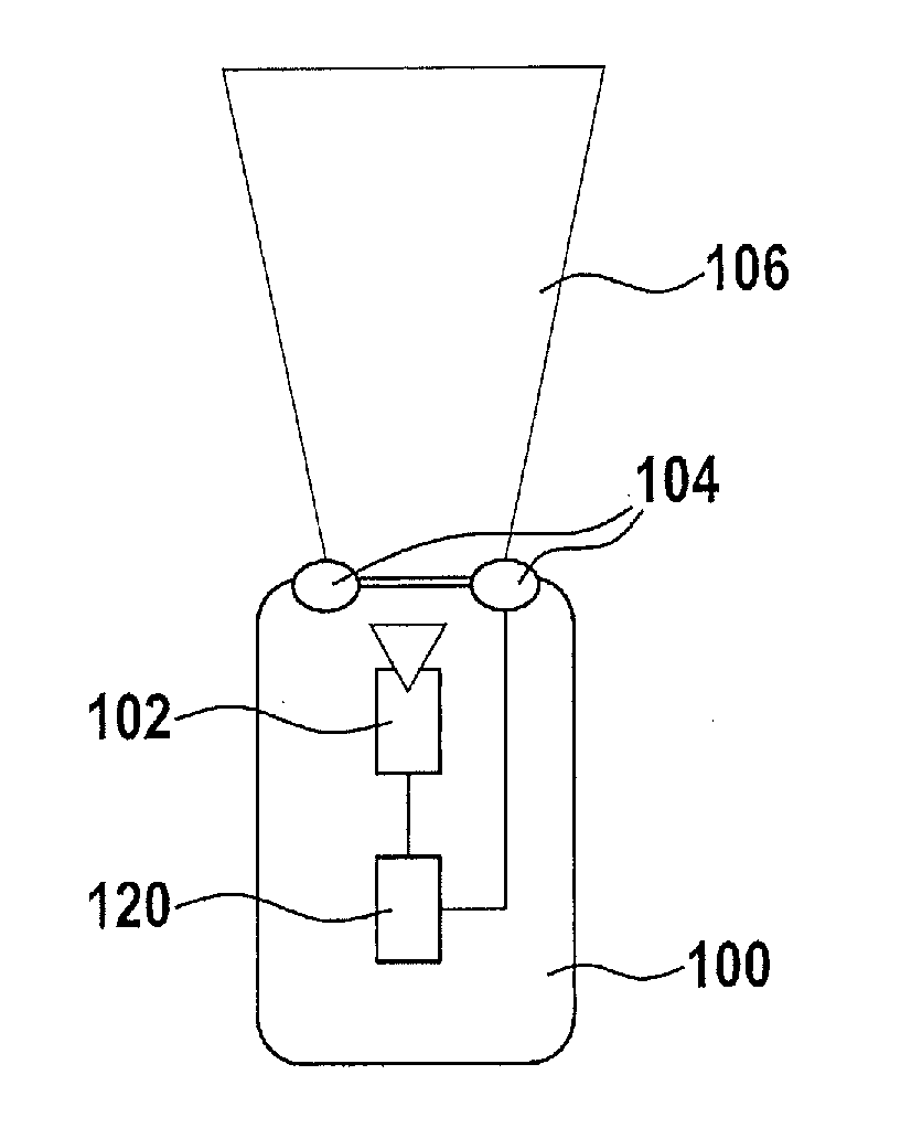
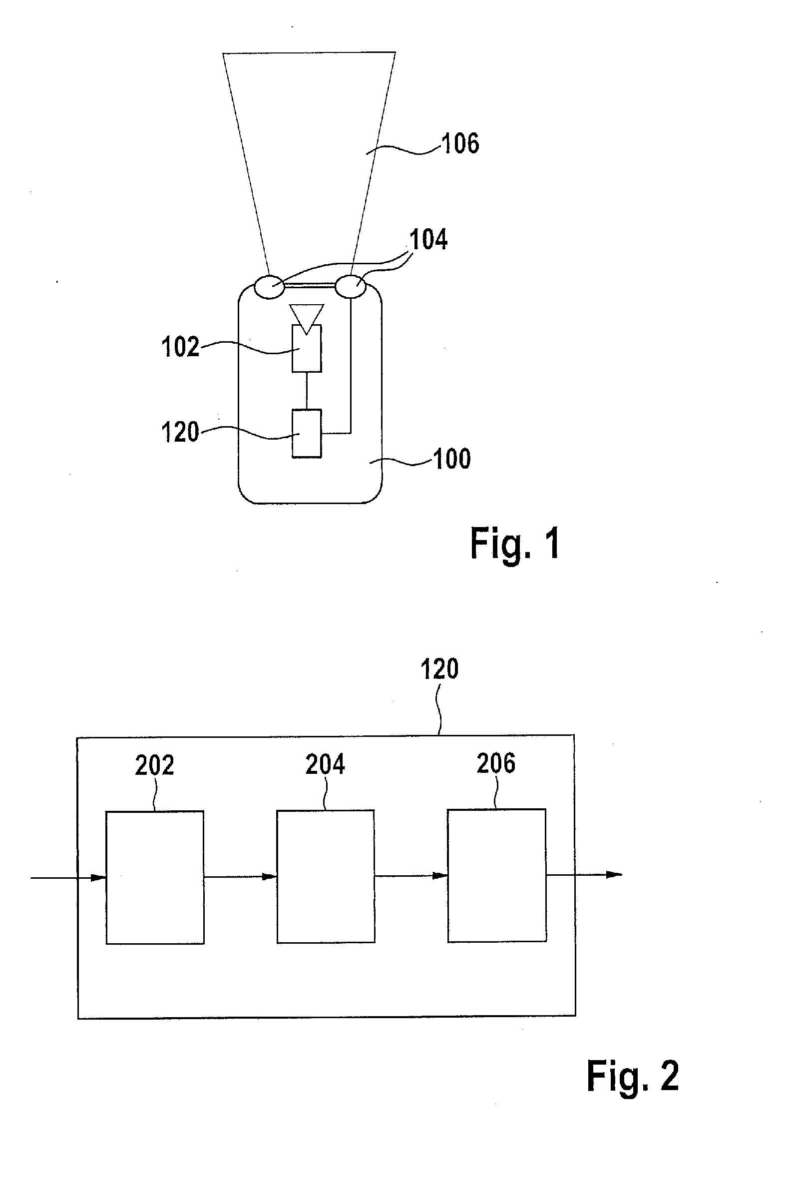
[0035]FIG. 1 shows an illustration of a vehicle 100 according to an exemplary embodiment of the present invention. Vehicle 100 has an environment-detection device 102, headlights 104 featuring low beam and high beam, as well as a control device 120 for switching on the high beam headlights. Environment-detection device 102 in this exemplary embodiment is a camera 102 with integrated object detection. The environment-detection device could just as well be a radar device, for example. The object detection is set up to detect other road users. It is furthermore designed to provide high-beam information if camera 102 does not detect any other road users in front of vehicle 100 in a glare zone 106 in ...


PUM


Abstract

A method for switching on a high-beam headlight of a vehicle includes: a step of receiving high-beam information by way of an interface, the high-beam information indicating a possibility of a glare-free operation of the high-beam headlight; a step of determining a traveled distance of the vehicle in response to receiving the high-beam information, and a step of supplying switch-on information for activating the high-beam headlight if the traveled distance after receiving the high-beam information is greater than a predefined minimum distance.

Description

BACKGROUND OF THE INVENTION[0001]1. Field of the Invention[0002]The present invention relates to a method for switching on a high beam headlight of a vehicle, to a control device for switching on a high beam headlight of a vehicle, and to a corresponding computer program product.[0003]2. Description of the Related Art[0004]A method for the automatic control of illumination devices, especially of a motor vehicle, using a brightness sensor is described in the published German patent application document DE 101 16 490 A1. The brightness sensor outputs signals, and following a time interval that begins at the instant at which the signals exceed or drop below a first threshold, the illumination devices are switched off. The length of the time interval is variable and can be increased, in particular.BRIEF SUMMARY OF THE INVENTION[0005]Against this backdrop, the present invention introduces a method for switching on a high beam headlight of a vehicle, a control device for switching on a hi...

Claims


Application Information

Patent Timeline
Patent Type & Authority Applications(United States)
IPC IPC(8): B60Q1/08
CPCB60Q1/08B60Q1/143B60Q2300/112B60Q2300/136B60Q2300/305B60Q2300/314B60Q2300/32B60Q2300/41B60Q2300/42
Inventor EHLGEN, TOBIASFOLTIN, JOHANNESMEISNER, ROBERT
Owner ROBERT BOSCH GMBH
Why Eureka
Try Eureka