Traffic cone assembly

Inactive Publication Date: 2014-01-16
SUN YUEH CHE
View PDF2 Cites 8 Cited by
  • Summary
  • Abstract
  • Description
  • Claims
  • Application Information

AI Technical Summary

Benefits of technology

[0009]The main objective of the invention is to pro

Problems solved by technology

Accordingly, the visibility of the conventional traffic cone 80 is about 20 meters and is insufficient, especially in heavy rain or mist.
Consequently, the conventional tra

Method used


Image

  • Traffic cone assembly
  • Traffic cone assembly
  • Traffic cone assembly

Examples


Example

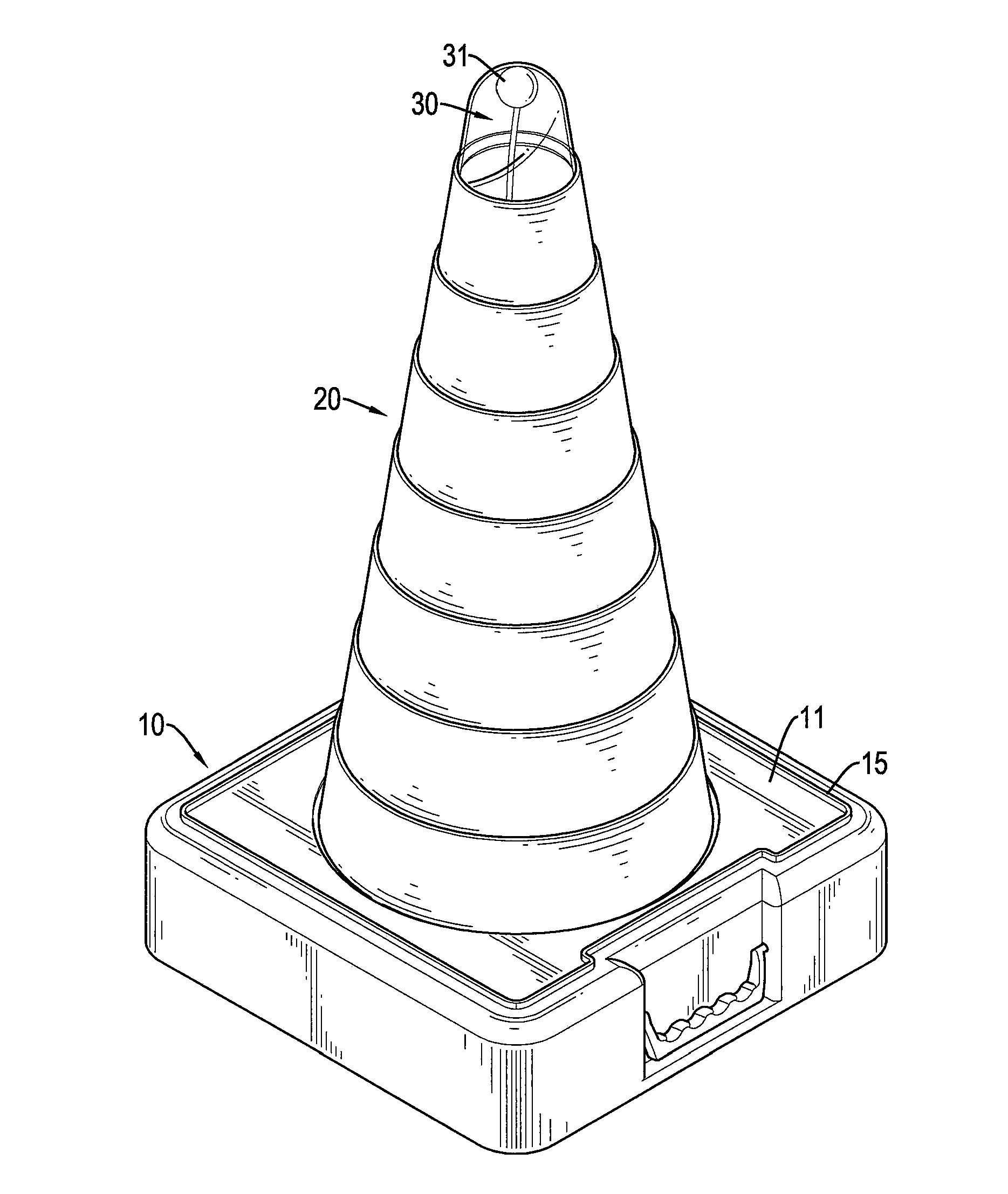
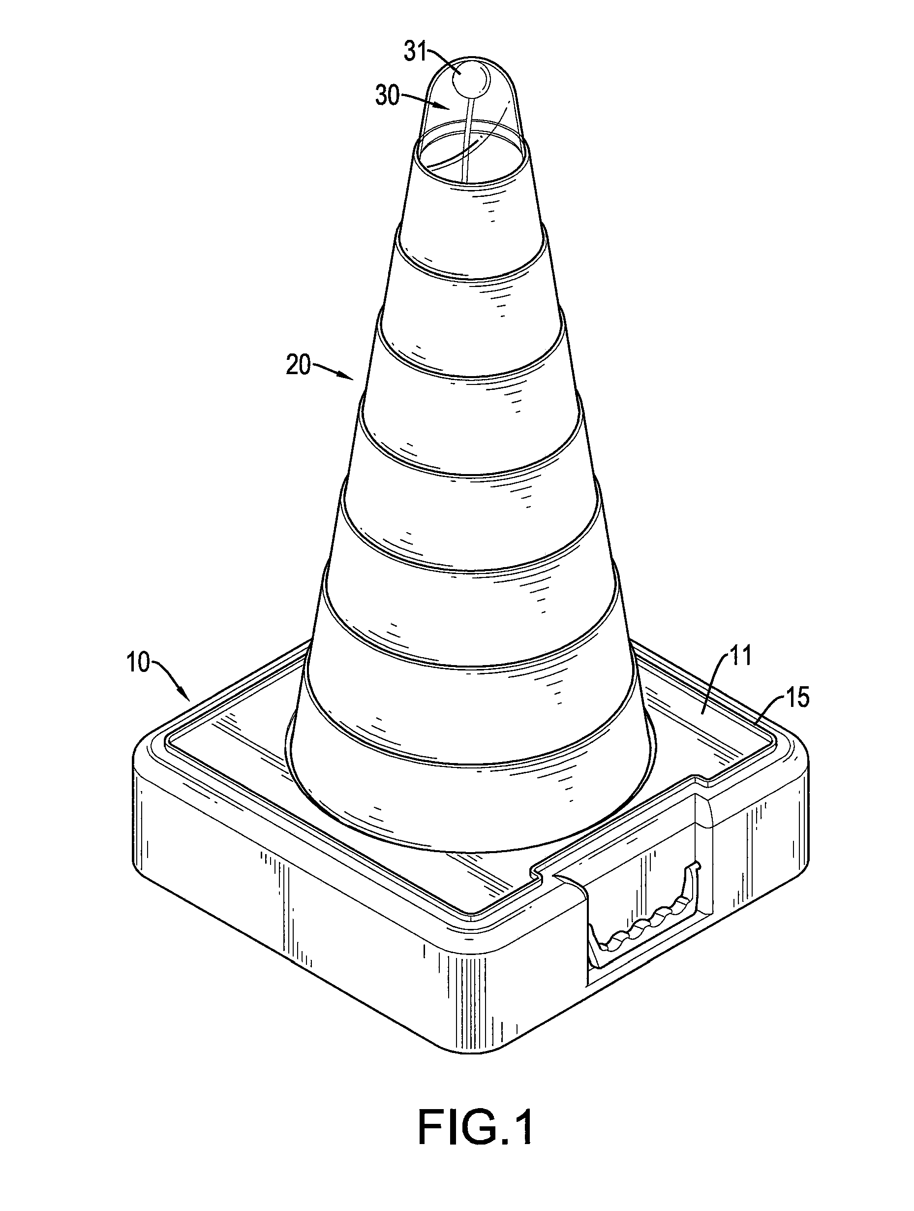
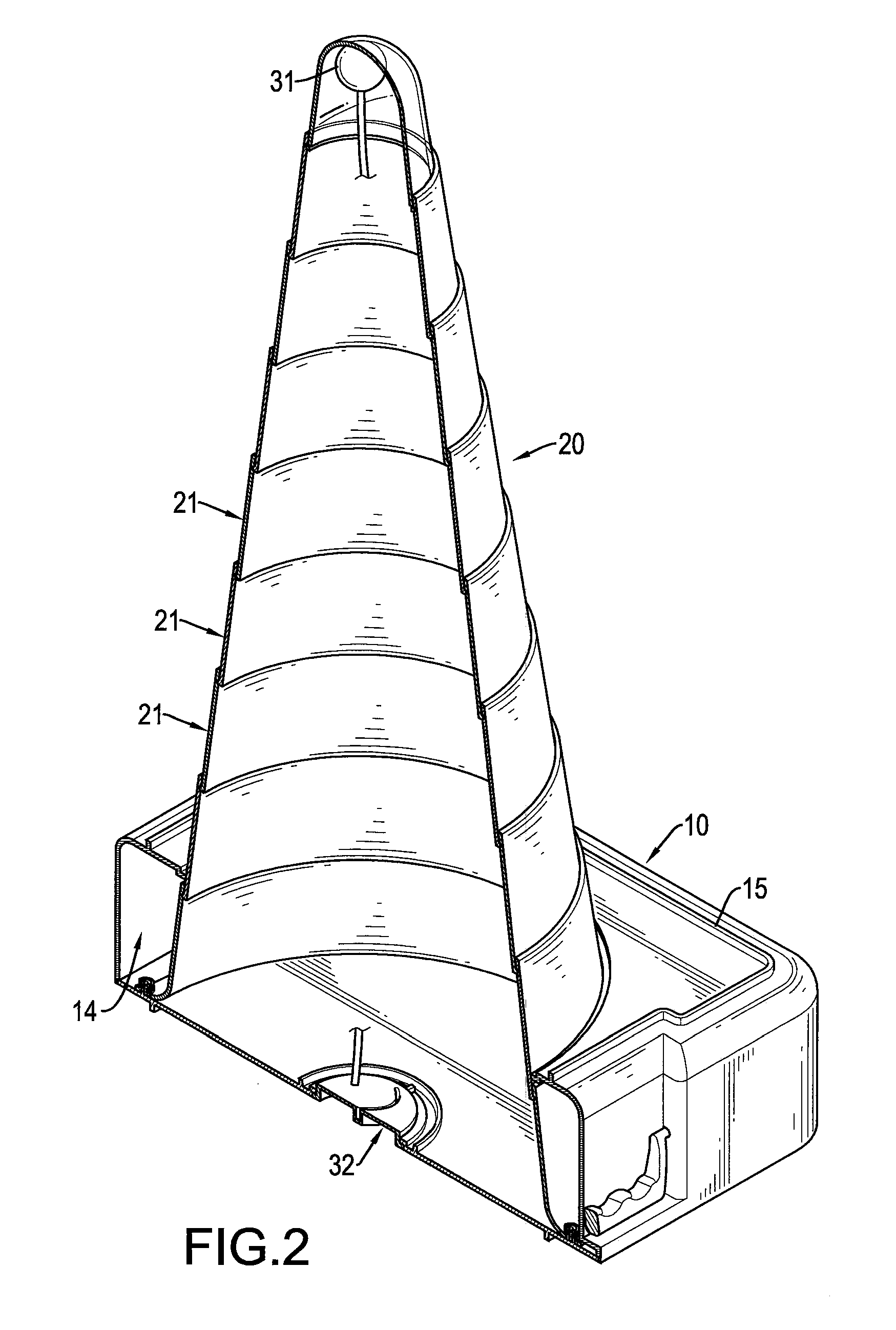
[0020]With reference to FIGS. 1 to 3, a traffic cone assembly in accordance with the present invention comprises a base 10, a telescopic unit 20 and an illuminating unit 30.

[0021]With reference to FIGS. 1 to 3 and 6, the hollow base 10 is a box and has a top surface 11, a bottom surface 12, a base hole 13 and an inner space 14. The bottom surface 12 of the base 10 is opposite to the top surface 11 of the base 10. The base hole 13 is round, is formed through the top surface 11 of the base 10 and communicates with the inner space 14 of the base 10.

[0022]Preferably, the base 10 has a top rib 15 and a bottom rib 16. The top rib 15 is loop-shaped and is mounted on the top surface 11 of the base 10. The bottom rib 16 is loop-shaped, is mounted on the bottom surface 12 of the base 10 and has a shape the same as that of the top rib 15. An outer surface of the bottom rib 16 of the traffic cone assembly is capable of abutting an inner surface of the top rib 15 of another traffic cone assembly...


PUM


Abstract

A traffic cone assembly has a base, a telescopic unit and an illuminating unit. The base has an inner space and a base hole formed through a top surface of the base. The telescopic unit is capable of telescoping longitudinally, is securely connected with the base and has a bottom, a middle and a top. The bottom of the telescopic unit is securely mounted in the inner space of the base. The middle of the telescopic unit protrudes out from the base hole. An LED (light emitting diode) of the illuminating unit is securely mounted on the top of the telescopic unit. Because the LED mounted on the top of the telescopic unit can illuminate, the traffic cone assembly can be seen with good visibility.

Description

BACKGROUND OF THE INVENTION[0001]1. Field of the Invention[0002]The present invention relates to a traffic cone assembly, and more particularly to a traffic cone assembly having good visibility.[0003]2. Description of Related Art[0004]With reference to FIG. 8, a conventional traffic cone 80 has a base 81, a cone 82 and a light-reflecting strip 83. The base 81 is a rectangular plate. The cone 82 is securely mounted on a top of the base 81. The light-reflecting strip 83 is securely mounted around a top of the cone 82.[0005]The traffic cone 80 is a marker that is placed on roads or sidewalks to temporarily redirect traffic in a safe manner. The traffic cone 80 is often used to separate or merge lanes during road construction projects or automobile accidents.[0006]Although the light-reflecting strip 83 can reflect light, the light-reflecting strip 83 does not illuminate. Accordingly, the visibility of the conventional traffic cone 80 is about 20 meters and is insufficient, especially in...

Claims


Application Information

Patent Timeline
IPC IPC(8): G08G1/0955
CPCE01F9/615E01F9/654E01F9/688
Inventor SUN, YUEH-CHE
Owner SUN YUEH CHE
Why Eureka
Try Eureka