Developer supply container and developer supplying system

a technology of supply container and supply system, applied in the direction of instruments, electrographic process equipment, optics, etc., can solve the problems of inability to properly reciprocate the pump portion, the reciprocation of the pump portion will be disabled, and the image formation will become impossible sooner or later

Active Publication Date: 2014-01-16
CANON KK
View PDF2 Cites 31 Cited by
  • Summary
  • Abstract
  • Description
  • Claims
  • Application Information

AI Technical Summary

Benefits of technology

The present invention provides a developer supply container and a developer supplying system that have properly operable feeding and pump portions, allowing for proper feeding and discharging of the developer.

Problems solved by technology

However, when such a structure is employed, a problem may arise.
That is, the problem arises in the case that the developer supply container is provided with a drive inputting portion for rotating the feeding portion and is also provided with a drive inputting portion for reciprocating the pump portion.
However, the pump portion may not be properly reciprocated in such a case that the developer supply container is taken out of the image forming apparatus and then is remounted.
As a result, the driving connection is not properly established between the drive outputting portion of the image forming apparatus side and the drive inputting portion of the developer supply container side, and therefore, the reciprocation of the pump portion will be disabled.
Then, the developer supply into the image forming apparatus is not carried out, and the image formation will become impossible sooner or later.
Such a problem may similarly arise when the expansion and contraction state of the pump portion is changed by the user while the developer supply container is outside the apparatus.

Method used


Image

  • Developer supply container and developer supplying system
  • Developer supply container and developer supplying system
  • Developer supply container and developer supplying system

Examples


embodiment 1

[0072]First, basic structures of an image forming apparatus will be described, and then, a developer supplying system, that is, a developer replenishing apparatus and a developer supply container used in the image forming apparatus will be described.

(Image Forming Apparatus)

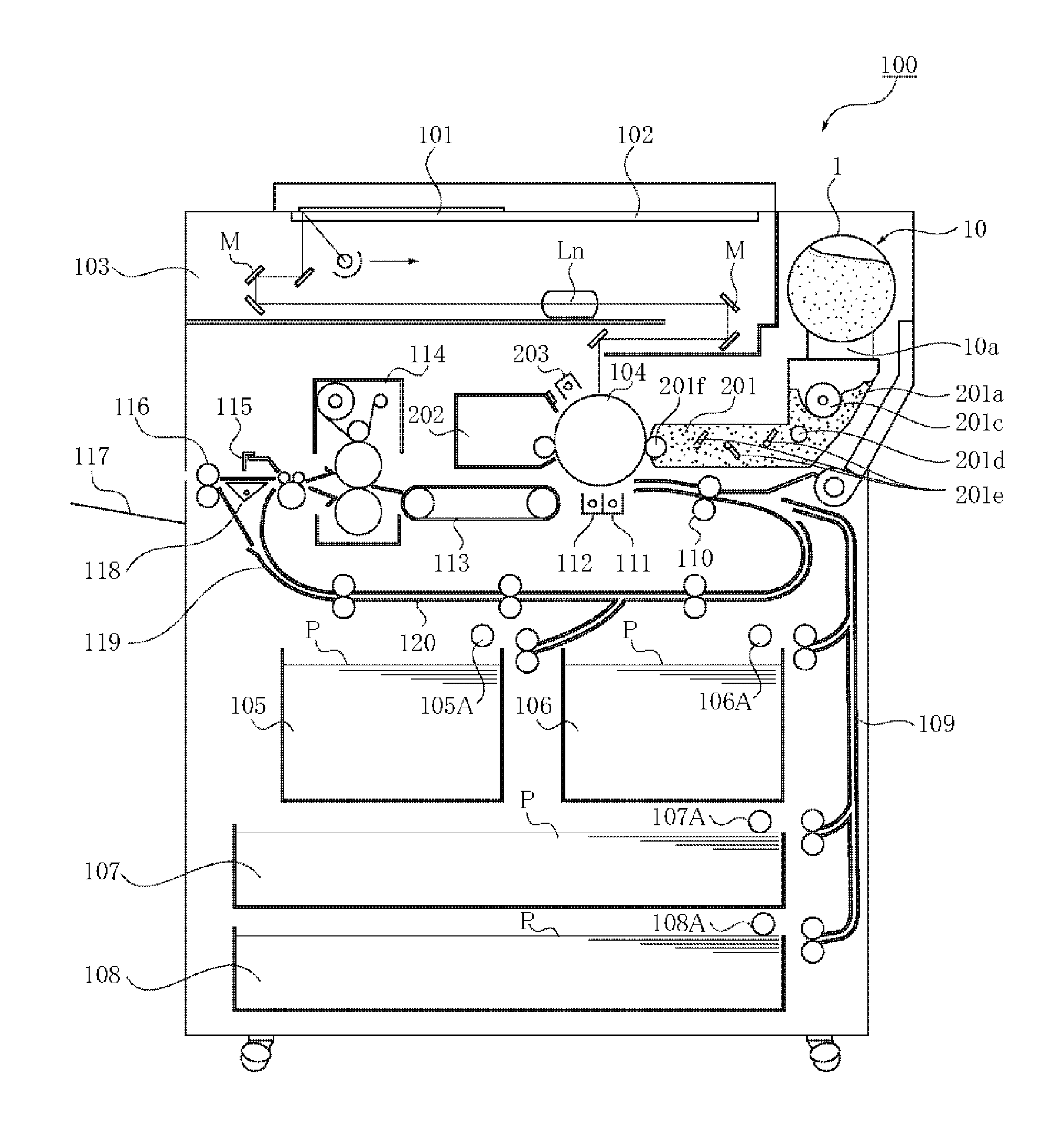
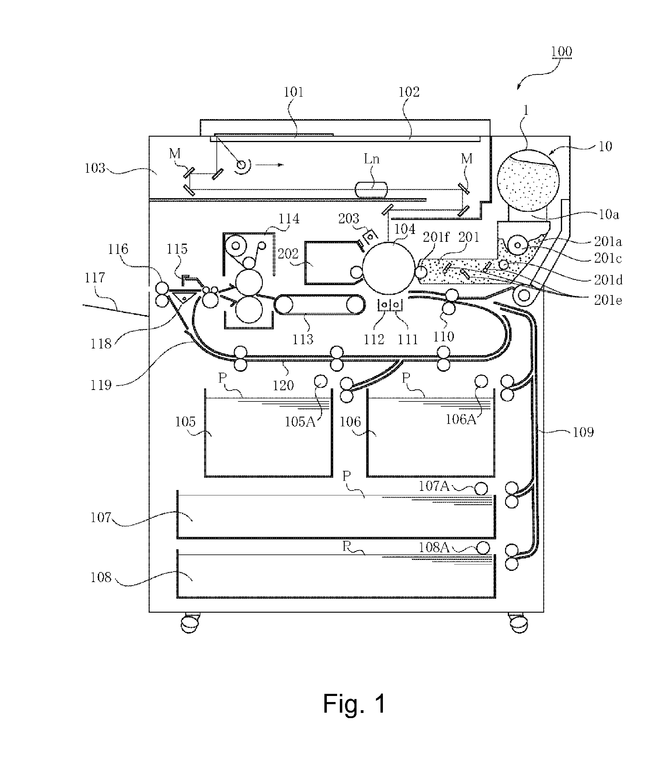
[0073]Referring to FIG. 1, the description will be made as to structures of a copying machine (electrophotographic image forming apparatus) employing an electrophotographic type process as an example of an image forming apparatus using a developer replenishing apparatus to which a developer supply container (so-called toner cartridge) is detachably mountable.

[0074]In the Figure, designated by 100 is a main assembly of the copying machine (main assembly of the image forming apparatus or main assembly of the apparatus). Designated by 101 is an original which is placed on an original supporting platen glass 102. A light image corresponding to image information of the original is imaged on an electrophotographic phot...

embodiment 2

[0296]Referring to FIG. 23 (parts (a) and (b)), structures of the Embodiment 2 will be described. Part (a) of the FIG. 23 is a schematic perspective view of the developer supply container 1, and part (b) of the FIG. 23 is a schematic sectional view illustrating a state in which a pump portion 2b expands. In this example, the same reference numerals as in Embodiment 1 are assigned to the elements having the corresponding functions in this embodiment, and the detailed description thereof is omitted.

[0297]In this example, a drive converting mechanism (cam mechanism) is provided together with a pump portion 2b in a position dividing a cylindrical portion 2k with respect to a rotational axis direction of the developer supply container 1, as is significantly different from Embodiment 1. The other structures are substantially similar to the structures of Embodiment 1.

[0298]As shown in part (a) of FIG. 23, in this example, the cylindrical portion 2k which feeds the developer toward a discha...

embodiment 3

[0307]Referring to FIG. 24, the structures of Embodiment 3 will be described. In this example, the same reference numerals as in the foregoing embodiments are assigned to the elements having the corresponding functions in this embodiment, and the detailed description thereof is omitted.

[0308]This example is significantly different from Embodiment 1 in that a drive converting mechanism (cam mechanism) is provided at an upstream end of the developer supply container 1 with respect to the feeding direction for the developer and in that the developer in the cylindrical portion 2k is fed using a stirring member 2m. The other structures are substantially similar to the structures of Embodiment 1.

[0309]As shown in FIG. 24, in this example, the stirring member 2m is provided in the cylindrical portion 2k as the feeding portion and rotates relative to the cylindrical portion 2k. The stirring member 2m rotates by the rotational force received by the gear portion 2a, relative to the cylindrica...


PUM


Abstract

In the case that a developer supply container is provided with a feeding portion for feeding a developer by receiving a rotational force and a pump portion for discharging the developer by reciprocation, and the rotational force and a reciprocating force are received from a main assembly side of an image forming apparatus, there is a liability that a driving connection is not properly established between a portion of the developer supply container for receiving the reciprocating force and a portion of the main assembly side for applying the reciprocating force.The developer supply container is provided with a drive converting mechanism for converting the rotational force received from the main assembly side to a force for operating a volume changing type pump.

Description

FIELD OF THE INVENTION[0001]The present invention relates to a developer supply container detachably mountable to a developer replenishing apparatus and to a developer supplying system including them. The developer supply container and the developer supplying system are used with an image forming apparatus such as a copying machine, a facsimile machine, a printer or a complex machine having functions of a plurality of such machines.BACKGROUND ART[0002]Conventionally, an image forming apparatus such as an electrophotographic copying machine uses a developer of fine particles. In such an image forming apparatus, the developer is supplied from the developer supply container in response to consumption thereof resulting from image forming operation.[0003]As for the conventional developer supply container, an example is disclosed in Japanese Laid-Open Utility Model Application Sho 63-6464.[0004]In the apparatus disclosed in Japanese Laid-Open Utility Model Application Sho 63-6464, the dev...

Claims


Application Information

Patent Timeline
Patent Type & Authority Applications(United States)
IPC IPC(8): G03G15/08
CPCG03G15/0865G03G2215/0685G03G15/0872G03G15/0877G03G15/0808G03G15/0849G03G15/0867
Inventor MURAKAMI, KATSUYANAGASHIMA, TOSHIAKITAZAWA, FUMIOOKINO, AYATOMOYAMADA, YUSUKE
Owner CANON KK
Why Eureka
Try Eureka