
Methodology and apparatus for storing and dispensing liquid components to create custom formulations

a technology for liquid components and custom formulations, applied in liquid dispensing, rigid containers, special dispensing means, etc., can solve the problems of physical tax on the operator, drawbacks and disadvantages of manual methods of dispensing formulations, and the most costly expense of operator handling in creating custom formulations, so as to reduce the amount of base materials and reduce material opportunities

Inactive Publication Date: 2010-09-07
GFI INNOVATIONS
View PDF55 Cites 18 Cited by
  • Summary
  • Abstract
  • Description
  • Claims
  • Application Information

AI Technical Summary

Benefits of technology

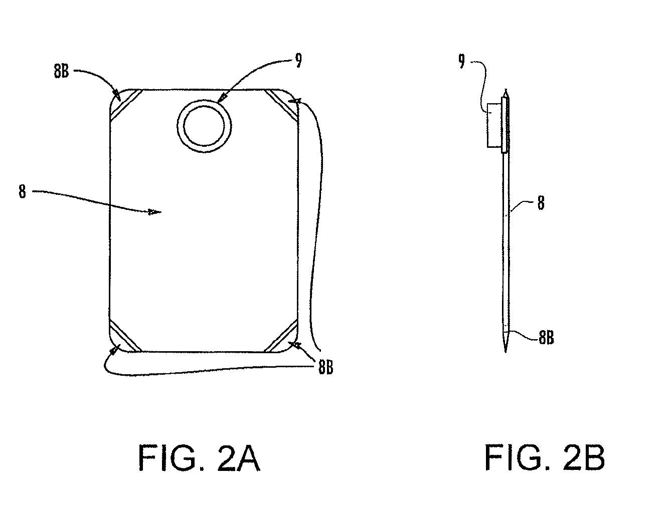
[0031]The bag has a top, bottom and sides, sealed airtight, and also has a centered opening adjacent to the top in the form of a hole large enough to accept the clear passage of a molded fitting secured into it, becoming an integral part of the material bag. The bag also has a bag spout that provides for: 1) an opening in which to fill the material bag with material; 2) an opening in which to evacuate the material bag of material; 3) a means of connecting material bag to the dispenser; and 4) a means of connecting a pressure responsive silicone dispense valve to it. The material bag may incorporate a proportional elastomeric dispense valve or pressure responsive dispense valve. The material bag may also have a delta seal (a sealed-tight seam on an angle to its starting point) on any one its four corners, each of which may decrease the opportunity for material to become trapped within that area and which directs material in the direction of the bag spout throughout the process of evacuation of material from the material bag when pressure is applied to the material bag.
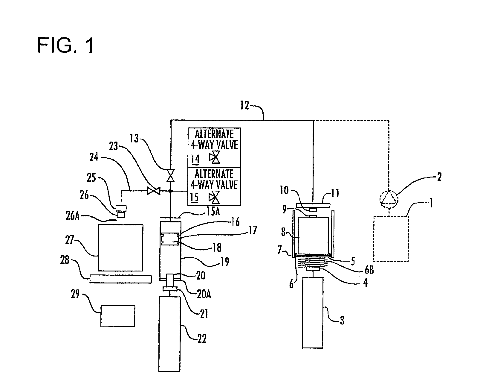
[0032]Another aspect of the present invention is an improved container, such as a cylindrical container or a material cartridge, that incorporates the proportional elastomeric dispense valve or pressure responsive dispense valve into the discharging end of the container. The dispense valve opens and closes rollingly in response to a predetermined discharge force, allowing stored material to precisely discharge from the container.
[0033]Still another aspect of the present invention is an improved movable member such as a puck (residing within the material container used to push the base material out of the container). The improved puck includes a number of seals around it's outside edge which effectively presses base material out of the material container through the dispense valve without allowing the material to bypass the puck. Additionally, the puck has a convex center that permits ample room for the dispense valve (found centered on the fixed end of the cartridge container) to close when the puck comes in direct contact with the fixed end of the cartridge. The puck is angled or configured on its bottom in such a way as to mate up with the fixed end of the container to decrease the amount of base material that may remain after the puck comes in contact with the fixed end of the container and subsequently provides the greatest opportunity for all of the base material in the container to be expelled from the container.

Problems solved by technology

Drawbacks and disadvantages exist with respect to the Manual Method of dispensing formulations.
For example, operator handling is the most costly expense of creating custom formulations when using the Manual Mix Method.
The process of scooping the material from the buckets is physically taxing on the operator and can be a very messy operation due to the stringing nature of the material.
If the material is highly viscous the operator can more easily remove material from the amount added (if the amount added were too high) than if the material were less viscous in which case the material added may disperse into the material already in the receiving container, not allowing for removal of the amount over added.
If too much of a given material of the formulation is manually added, additional amounts of the other components required of the formulation would proportionally need to be added, resulting in the creation of more finished product than originally requested, potentially resulting in material waste.
Similarly, there are some drawbacks and disadvantages with the Gravimetric / Pump Dispenser Method.
Some of the major drawbacks experienced with this method are dispense valve actuation, dispensing time, accurate reporting, scale cost, effect of vibration and wind currents, pump wear and cost, air fluctuation, and multiple scale cost.
The delay created in an air signal needing to travel through an air line to the pneumatic solenoid affects how fast the dispense valve can physically open and close.
Another drawback involves time delays in dispensing materials.
There are time added delays due to the scale needing to completely stop its movement after each dispense in order that the computer can activate the pump to dispense more product, if required.
Yet another disadvantage with Gravimetric / Pump Dispensers relates to the costs of the scales needed with those systems.
Some Gravimetric / Pump Dispensers may use several scales of varying capacities that add significantly to the cost of the Gravimetric / Pump Dispenser.
In addition, scales can be susceptible to vibration and air movement due to their sensitive load cells.
This problem could cause time delays and inaccurate readings of the actual dispense if the scale is not shrouded by a cover.
Yet another drawback involves the pumps used with the Gravimetric / Pump Dispensers.
A costly pump is required for each material component.
The pumps add considerable upfront expense and ongoing maintenance expenses to the system.
The cost of maintenance is high due to the fact that the pumps, being mechanical devices, inherently are subject to a high degree of wear and tear.
Failure of the seals that provide the pumping ability is the most common maintenance issue with pumps.
Air compressors struggle with the delivery of consistent air pressure which the dispense valve relies on to accurately dispense to the scale.
Moreover, there are disadvantages and drawbacks related to the transportation, storage and disposal of known material containers.
For instance, there can be high costs relating to residual waste of material in a container when the material in the container is used and the container is disposed of.
If all of the material in the bucket is not used when the lid is first removed, and the lid is repeatedly removed and replaced, over the course of time the material in the bucket, especially that material that may not have been sufficiently removed from the side walls of the bucket, tends to skin-over or may become crusty, rendering it useless and adding to the amount of wasted material.
Occasionally, the dried or contaminated material on the sidewalls contaminates the remaining “good” material in the bottom of the bucket, rendering the good material difficult to work with, making it more subject to operator disposal.
Additionally, on the bottom of a bucket, due to the bucket's construction, areas could be present where ink becomes trapped and the complete removal of the ink from the bucket becomes virtually impossible.
If all of the material in the HDPE jug container is not used when the cap is first removed, and the cap is repeatedly removed and replaced, over the course of time the material in the HDPE jug container, especially that material that may not have been sufficiently removed from the side walls of the HDPE jug container, tends to skin-over or may become crusty, rendering it useless and adding to the amount of wasted material.
Occasionally, the dried or contaminated material on the sidewalls of the HDPE jug container contaminates the remaining “good” material in the bottom of the HDPE jug container, rendering the good material difficult to work with, making it more subject to operator disposal.
Additionally, on the bottom and on the sidewalls of an HDPE jug container, due to the HDPE jug container construction and the small opening, areas could be present where ink becomes trapped and the complete removal of the ink from the HDPE jug container becomes virtually impossible.
Additionally, there are drawbacks with respect to known cardboard-roll or plastic tubes that result in material waste in those containers.
However, with known tube designs, an area remains between the puck and the fixed end of the tube, creating a region for the material in the tube to remain and not be discharged thus creating waste when the tube is disposed of.

Method used


Image

  • Methodology and apparatus for storing and dispensing liquid components to create custom formulations
  • Methodology and apparatus for storing and dispensing liquid components to create custom formulations
  • Methodology and apparatus for storing and dispensing liquid components to create custom formulations

Examples


Embodiment Construction

[0056]The present invention may be embodied in many forms and many methodologies. As used herein, the following terms have the following broad meaning as understood by those of skill in the art. Note that these definitions are intended to simply assist the reader in understanding the terms used herein and are not meant to provide a limiting definition to each term. The term “material” means a flowable, non-solid substance, such as liquid, paste or powder, or any other substance capable of dispensing. The term “formulation” means a prescribed recipe of a number of material components typically divided, according to their individual requirements, by percentages that, when dispersed or thoroughly mixed together, create a desired finished product. The terms “container” or “material container” mean any and all devices or structures, in which one or more materials may be contained, held, packaged into, received in, stored in or used as delivery package, including without limitation any an...


PUM

PropertyMeasurementUnit
weightaaaaaaaaaa
air pressureaaaaaaaaaa
liquidaaaaaaaaaa

Abstract

The invention is directed to methodologies and apparatuses in which materials are dispensed in order to create a desired finished product. The invention includes a material dispenser that further includes a container containing material, a press plate or puck for exerting pressure on the material, a sensor for detecting the material discharged from the container, and a scale for detecting the amount of material discharged from the container. The sensor and scale provide feedback to a computer which controls the amount of pressure exerted on the material. The computer controls the pulsing of additional material from the container until a targeted amount of material has been discharged from the container. The invention permits the dispensing of a specific amount of material in a controllable, metered fashion.

Description

CROSS-REFERENCE TO RELATED APPLICATIONS[0001]This application is a divisional of U.S. application Ser. No. 11 / 248,064, filed Oct. 12, 2005, which is a continuation-in-part of U.S. application Ser. No. 10 / 628,320, filed Jul. 28, 2003, now U.S. Pat. No. 7,198,073, which claims priority to U.S. Provisional Application Ser. No. 60 / 456,746, filed Mar. 21, 2003. U.S. application Ser. No. 11 / 248,064 also claims priority to U.S. Provisional Application Ser. No. 60 / 640,000, filed Dec. 29, 2004 and U.S. Provisional Application Ser. No. 60 / 640,001, filed Dec. 29, 2004.FIELD OF THE INVENTION[0002]The present invention relates to dispensing a specific amount of material from one container into another container.BACKGROUND OF THE INVENTION[0003]There are many different types of material dispensers available to the market offering differing levels of automation. Choosing one type of dispenser over another is often a function of what type of material is needing to be dispensed and is further define...

Claims


Application Information

Patent Timeline
Patent Type & Authority Patents(United States)
IPC IPC(8): B65B1/04B65B3/04B67D7/72
CPCB01F13/1058B01F13/1063B01F15/0201B01F15/0203B01F15/0216B01F15/0237B01F15/0238B01F15/0445B01F2215/0059B01F33/841B01F33/8442B01F35/714B01F35/712B01F35/71745B01F35/7174B01F35/881B01F2101/35B01F35/71805
Inventor LUEHRSEN, ROBERT A.BORKOVEC, JOHNPEDRAZA, DEREK P.
Owner GFI INNOVATIONS
Learn More