Disk brake apparatus

Active Publication Date: 2009-01-15
HITACHI ASTEMO LTD
View PDF22 Cites 17 Cited by
  • Summary
  • Abstract
  • Description
  • Claims
  • Application Information

AI Technical Summary

Benefits of technology

[0010]In view of the above, it is an object of the invention to provide a disk brake apparatus which, while employing a simple structure, can remove the air of the hydraulic fluid charged into the cylinder hole positively and easily, thereby enhancing the efficiency of the operation and maintenance of the disk brake apparatus.
[0023]a substantially cylinder housing accommodates the fixed side cam plate, the drive side cam plate, the thrust transmission plate, a cam spring which energizes the thrust transmission plate in the direction of the drive side cam plate,
[0028]According to the disk brake apparatus of the invention, the air of the hydraulic fluid can be discharged properly through the communication holes formed in the housing and a liquid passage hole formed so as to communicate with the engaging grooves of the cylinder hole. Further, the air mixed into the hydraulic fluid within the housing can be discharged surely.
[0029]Further, since the engaging ribs provided on the housing are formed by cutting and raising the peripheral wall of the housing, spaces formed by cutting and raising the peripheral wall can be used as communication holes which allows the communication between the inside and outside of the housing. This eliminates need an operation of forming communication holes separately, thereby being able to reduce the cost of the disk brake apparatus.

Problems solved by technology

However, in the above-mentioned disk brake apparatus, it takes much time and troublesome to discharge air mixed in hydraulic fluid charged into the cylinder hole and, especially, in the housing, it is difficult to discharge the air of the hydraulic fluid therefrom, resulting in the poor efficiency of the operation of the disk brake apparatus.

Method used


Image

  • Disk brake apparatus
  • Disk brake apparatus
  • Disk brake apparatus

Examples


Embodiment Construction

[0034]Hereinafter, description will be given below in detail of a disk brake apparatus according to an embodiment of the invention with reference to the accompanying drawings.

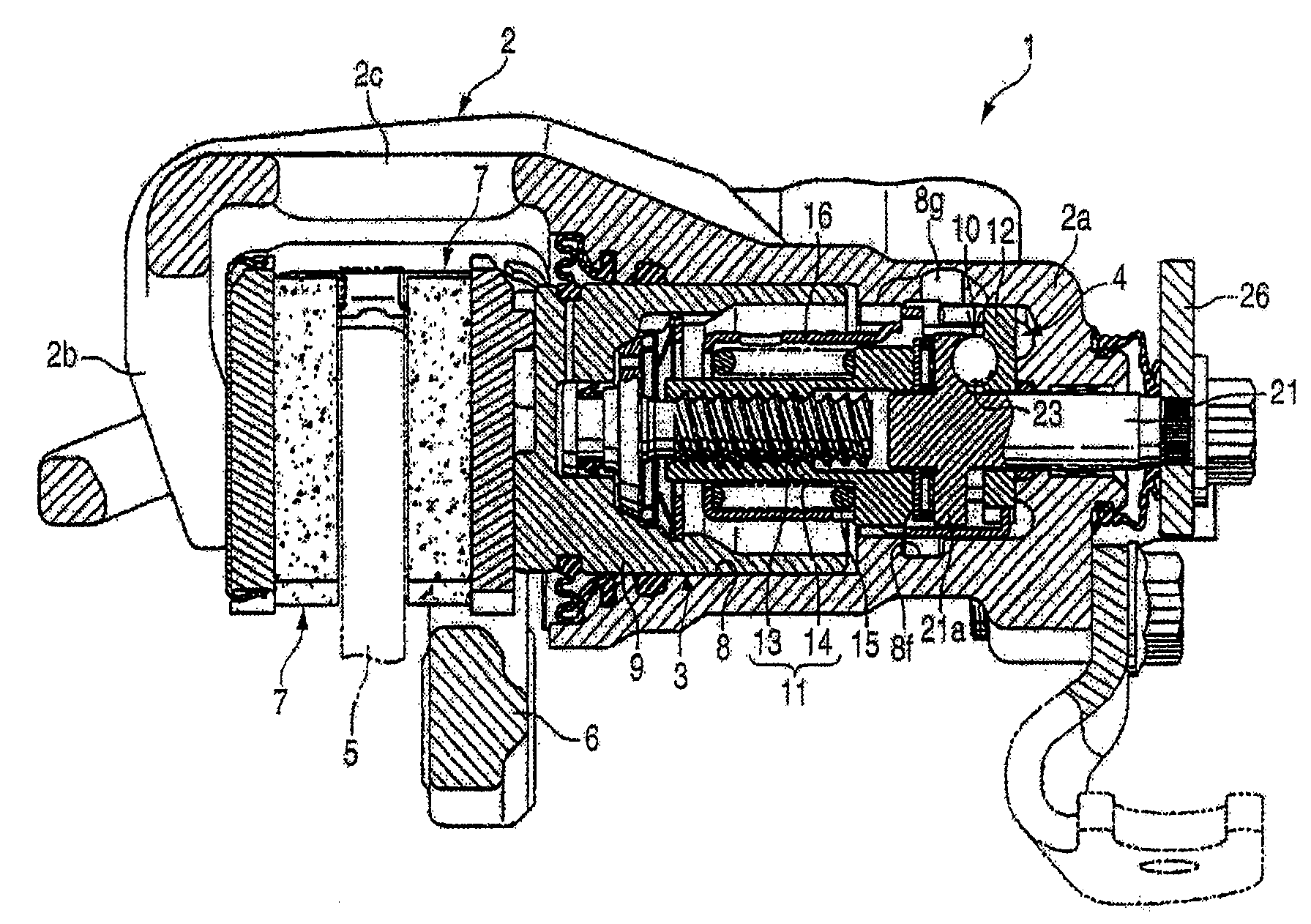
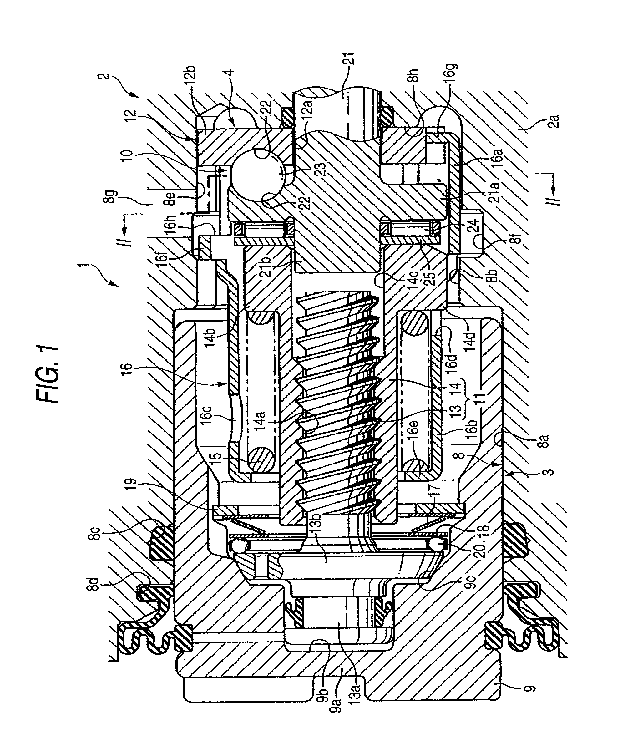
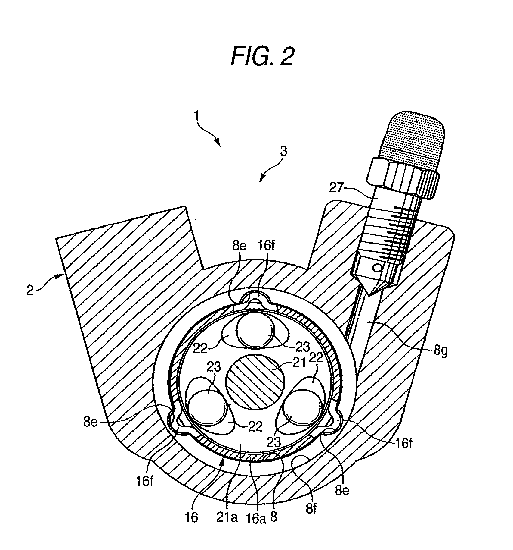
[0035]FIG. 1 is an enlarged section view of the main portions of the disk brake apparatus, FIG. 2 is a section view taken along the II-II line shown in FIG. 1, FIG. 3 is an exploded perspective view of a thrust conversion mechanism, an adjust nut and a housing respectively included in the disk brake apparatus, and FIG. 4 is a front section view of the disk brake apparatus.

[0036]A disk brake apparatus 1 according to the embodiment is a disk brake apparatus with a parking brake which includes, a hydraulic pressure type operation mechanism 3 operated by a brake pedal in a caliper body 2 and a mechanical type operation mechanism 4 for a parking brake operated by a hand lever or a foot pedal (neither of which are shown). The caliper body 2 is movably supported on a caliper bracket 6 to be fixed to a car body on one ...


PUM


Abstract

Engaging grooves 8e extending in the cylinder axial direction and circumferential grooves 8f formed in a cylinder axial direction middle portion of the engaging grooves 8 are formed on a bottom side of a cylinder hole 8. Engaging rib 12b engaging with the engaging groove 8e and engaging rib 16d which engages with the engaging groove 8e and fits to the circumferential groove 8f are formed on a fixed side cam plate 12 and a housing, respectively. A bleeder hole 8g which penetrates communicates with the engaging grooves 8e and circumferential grooves 8f of the cylinder hole 8 is drilled in a caliper body 2. Communication holes 16h which allow communication between the inside and outside of the housing 16 is formed at a bottom side of the cylinder hole 8 rather than the engaging rib 16f of the housing.

Description

BACKGROUND OF THE INVENTION[0001]1. Field of the Invention[0002]The present invention relates to a disk brake apparatus and, specifically, to a disk brake apparatus which includes a piston for pushing a friction pad in accordance with a hydraulic pressure, an adjuster for automatically adjusting a clearance between the friction pad and a disk rotor, and a parking brake for pushing the piston through the adjuster by a ball ramp type thrust conversion mechanism.[0003]2. Description of Related Art[0004]As disk brake apparatuses for use in a four-wheel drive car, there are known a disk brake apparatus with a parking brake which includes a hydraulic pressure type operation mechanism using a brake pedal and a mechanical type operation mechanism pulled and operated by a hand lever or a foot pedal.[0005]In this disk brake apparatus with a parking brake, generally, a piston constituting a hydraulic pressure type operation mechanism is disposed on a leading end opening side of a cylinder hole...

Claims


Application Information

Patent Timeline
IPC IPC(8): B60T1/06F16D65/18
CPCF16D65/18F16D65/567F16D2125/34F16D2121/14F16D2123/00F16D2121/02
Inventor WATADA, AKIFUMI
Owner HITACHI ASTEMO LTD
Why Eureka
Try Eureka