Cordless charging apparatus

Inactive Publication Date: 2014-01-16
SAMSUNG ELECTRONICS CO LTD
View PDF2 Cites 0 Cited by
  • Summary
  • Abstract
  • Description
  • Claims
  • Application Information

AI Technical Summary

Benefits of technology

[0012]The present invention has been made to address at least the problems and disadvantages described above, and to provide at least the advantages described below. Accordingly, aspects of the present invention provide a cordless charging apparatus which can minimize an electromagnetic interference between a cordless power rec

Problems solved by technology

That is, performance of the NFC antenna 16 becomes unstable due to a multiplying resonance generated by a f

Method used


Image

  • Cordless charging apparatus
  • Cordless charging apparatus
  • Cordless charging apparatus

Examples


Embodiment Construction

[0021]Hereinafter, embodiments of the present invention will be described with reference to the accompanying drawings. In the description, thicknesses of lines shown in the drawings and sizes of constituent elements may be exaggerated for clarity and convenience. Further, the following terms are defined considering their functions in the present invention and may be varied according to intentions and customs of a user or manager. Thus, the terms should be defined based on the contents of the entire specification. Further, although ordinal numbers such as first and second are used in the description of the embodiments of the present invention, their sequence may be arbitrarily determined and the description of the preceding elements may be applied to the description of the succeeding elements.

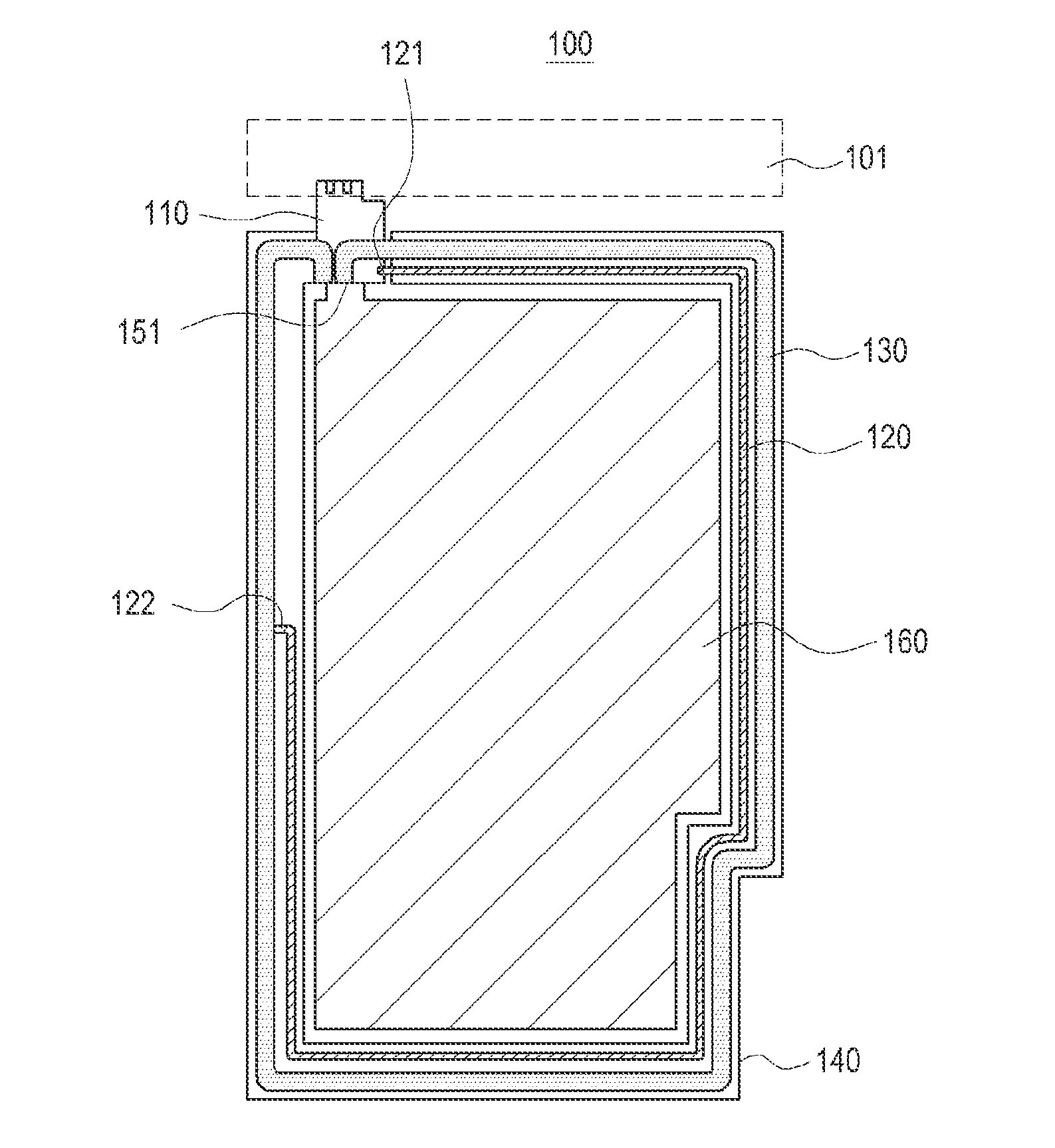
[0022]FIG. 3 illustrates one surface of a cordless charging apparatus according to an embodiment of the present invention. FIG. 4 illustrates another surface of the cordless charging apparatus a...


PUM


Abstract

A cordless charging apparatus is provided. The cordless charging apparatus includes a cordless power reception resonator including a feeding connector for electric feeding, and a ground connector for grounding. The ground connector is spaced apart from a connection terminal connecting the cordless power reception resonator to a circuit.

Description

PRIORITY[0001]This application claims priority under 35 U.S.C. §119(a) to Korean Application Serial No. 10-2012-0077129, which was filed in the Korean Intellectual Property Office on Jul. 16, 2012, the entire content of which is incorporated herein by reference.BACKGROUND OF THE INVENTION[0002]1. Field of the Invention[0003]The present invention relates generally to a cordless charging apparatus, and more particularly, to a cordless charging apparatus for restricting interference between frequencies of a Near Field Communication (NFC) antenna and a resonator of a cordless charging apparatus.[0004]2. Description of the Related Art[0005]In general, a portable terminal refers to a device by which a user can use a mobile communication function, an electronic note function, an Internet connection, and a multimedia function while carrying the device. Various functions have recently been integrated in one mobile communication terminal, which is generally referred to as a smart phone.[0006]...

Claims


Application Information

Patent Timeline
IPC IPC(8): H04B15/02H04B5/00
CPCH04B15/02H04B5/0037H04B5/0031H02J7/0042H02J50/12H02J50/005
Inventor KIM, JOON-ILPARK, SE-HOYEO, SUNG-KU
Owner SAMSUNG ELECTRONICS CO LTD
Why Eureka
Try Eureka