Microcontroller System for Identifying RF Coils in the Bore of a Magnetic Resonance Imaging System

Active Publication Date: 2009-06-11
INVIVO CORP
View PDF14 Cites 22 Cited by
  • Summary
  • Abstract
  • Description
  • Claims
  • Application Information

AI Technical Summary

Benefits of technology

[0008]In one aspect of the invention, an interface circuit for use in bore in a magnetic resonance imaging system is provided. The interface circuit is electrically connected to circuitry in the magnetic resonance imaging system to enable communications between the interface circuit and the magnetic resonance imaging system, and includes a controller, an isolation circuit electrically connected to the controller to isolate the controller from noise produced in the magnetic resonance im

Problems solved by technology

Identification and verification of the coil, however, is complicated

Method used


Image

  • Microcontroller System for Identifying RF Coils in the Bore of a Magnetic Resonance Imaging System
  • Microcontroller System for Identifying RF Coils in the Bore of a Magnetic Resonance Imaging System
  • Microcontroller System for Identifying RF Coils in the Bore of a Magnetic Resonance Imaging System

Examples


Embodiment Construction

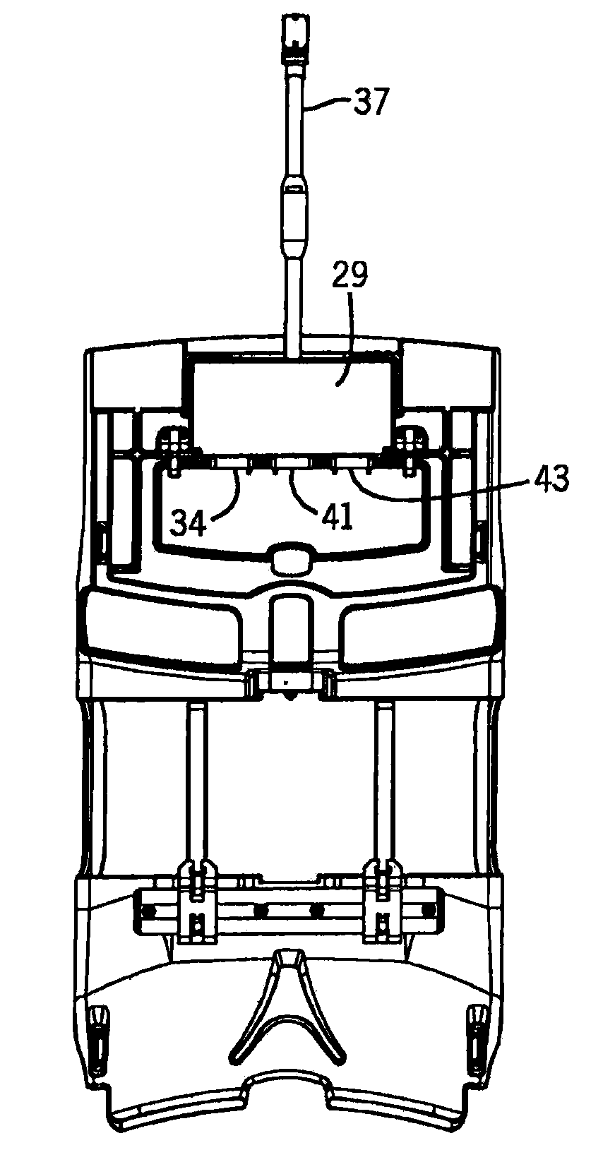
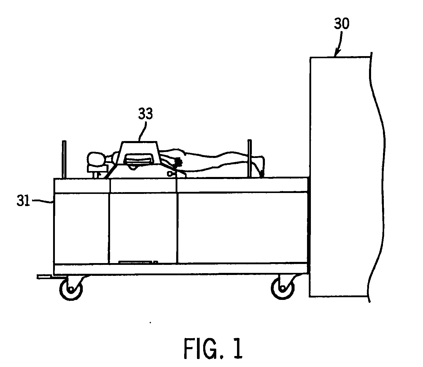
[0021]Referring to FIG. 1, the present invention is employed in an MRI system or scanner 30 of the type shown. The MRI system 30, as described above, includes a bore dimensioned to receive a patient for imaging. The patient lies on a patient transport 31, which can be, as shown here a wheeled structure. The patient is positioned on a tabletop sized to be received on the patient transport 31, and which can be selectively inserted into and removed from the bore. The transport 31 can also include a patient support 33 for supporting or immobilizing a specific portion of the anatomy to be imaged. As described below, the patient support 33 includes a plurality of connectors for receiving local RF coils at various positions on the support that are selected to provide imaging of the breast from a variety of angles and orientations. Although, as shown here, and as described below, the patient support 33 is configured for breast imaging, it will be apparent to those of ordinary skill in the a...


PUM


Abstract

A method and apparatus for identifying local RF coils in a MR system includes a microcontroller that is provided in the bore of the system. The microprocessor determines when local RF coils are connected, identifies the coils, and provides the information to an MR scanner. The controller is shielded to prevent electromagnetic interference.

Description

CROSS-REFERENCE TO RELATED APPLICATIONS[0001]This application claims the benefit of U.S. Provisional Application No. 60 / 989,898, filed Nov. 23, 2007, and U.S. Provisional Application No. 60 / 989,904, filed Nov. 23, 2007, which are hereby incorporated by reference.FIELD OF THE INVENTION[0002]The field of the invention relates to local radiofrequency (RF) coils used in magnetic resonance imaging (MRI), and more particularly to an interface for identifying RF coils and coil configurations in magnetic resonance imaging equipment.BACKGROUND OF THE INVENTION[0003]When a substance such as human tissue is subjected to a uniform magnetic field (polarizing field B0), the individual magnetic moments of the excited nuclei in the tissue attempt to align with this polarizing field. If the substance, or tissue, is subjected to a magnetic field (excitation field B1) that is in the x-y plane and that is near the Larmor frequency, the net aligned moment, Mz, may be rotated, or “tipped”, into the x-y p...

Claims


Application Information

Patent Timeline
IPC IPC(8): A61B5/055G01R33/28
CPCG01R33/341G01R33/546G01R33/36A61B5/704A61B5/708
Inventor HANSEN, JOHN W.RICHMOND, JOSHUA L.WANG, HANSELA, GAL
Owner INVIVO CORP
Why Eureka
Try Eureka