Apparatus for utilizing radiation energy

Inactive Publication Date: 2014-01-23
BANKWARE
View PDF4 Cites 6 Cited by
  • Summary
  • Abstract
  • Description
  • Claims
  • Application Information

AI Technical Summary

Benefits of technology

The technical effect of this disclosed invention is to improve the generation of heat and reduce heat loss in apparatuses that use radiation energy.

Problems solved by technology

Especially devices for transferring solar radiation energy, i.e. sunlight, into usable forms of energy, especially heat energy or electrical power, have experienced a remarkable raise in importance during the last years, even more due to increasing costs for fossil energy sources.
A significant disadvantage of this method is, that a major part of the collected heat is wasted by heating up structures, like walls of a working fluid container, which do not contribute to the actual working process.
Furthermore, the high temperatures necessary to reach acceptable efficiency values cause material stress and increased energy losses.
A high radiation density can result in high losses at the transfer unit due to a higher local radiation absorption in the material of the transfer unit.
In particular long wave radiation, like infrared radiation generated due to high temperatures of the working fluid, can pass said transfer unit and leak to the environment.
One may select a particle size that results in only minor adverse effects on the working process in said working unit.
In particular, a high particle density is assumed to cause a high viscosity of said working fluid and therefore impede the working process.

Method used


Image

  • Apparatus for utilizing radiation energy
  • Apparatus for utilizing radiation energy
  • Apparatus for utilizing radiation energy

Examples


Embodiment Construction

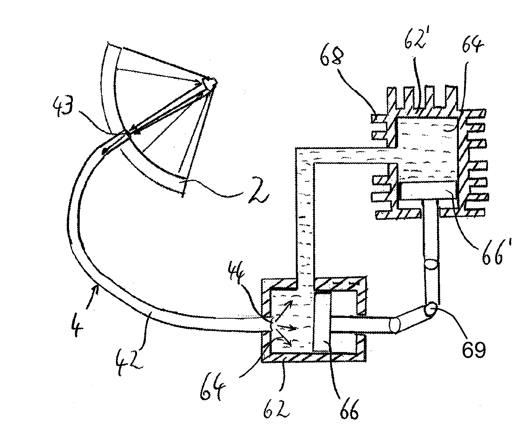
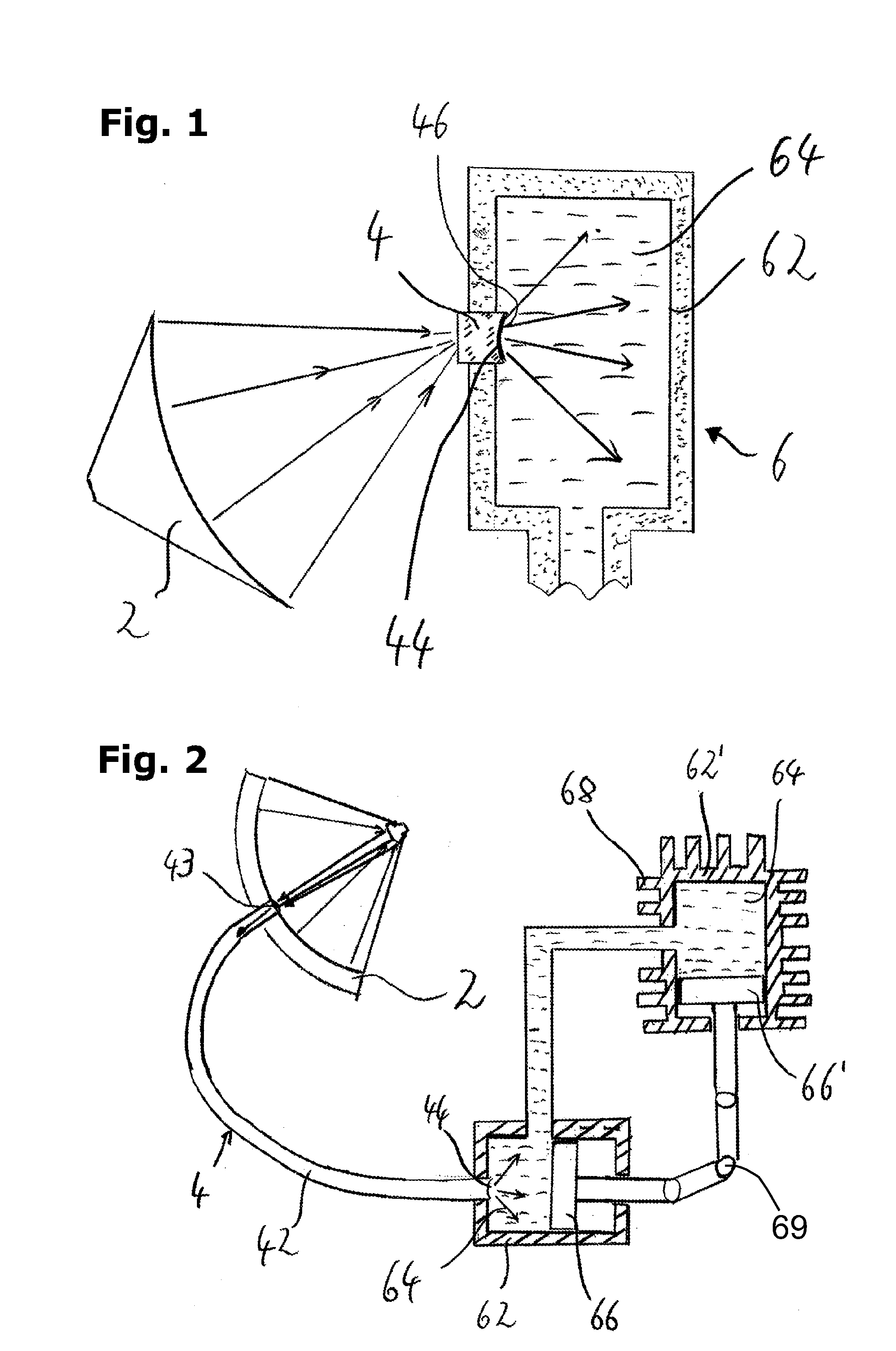
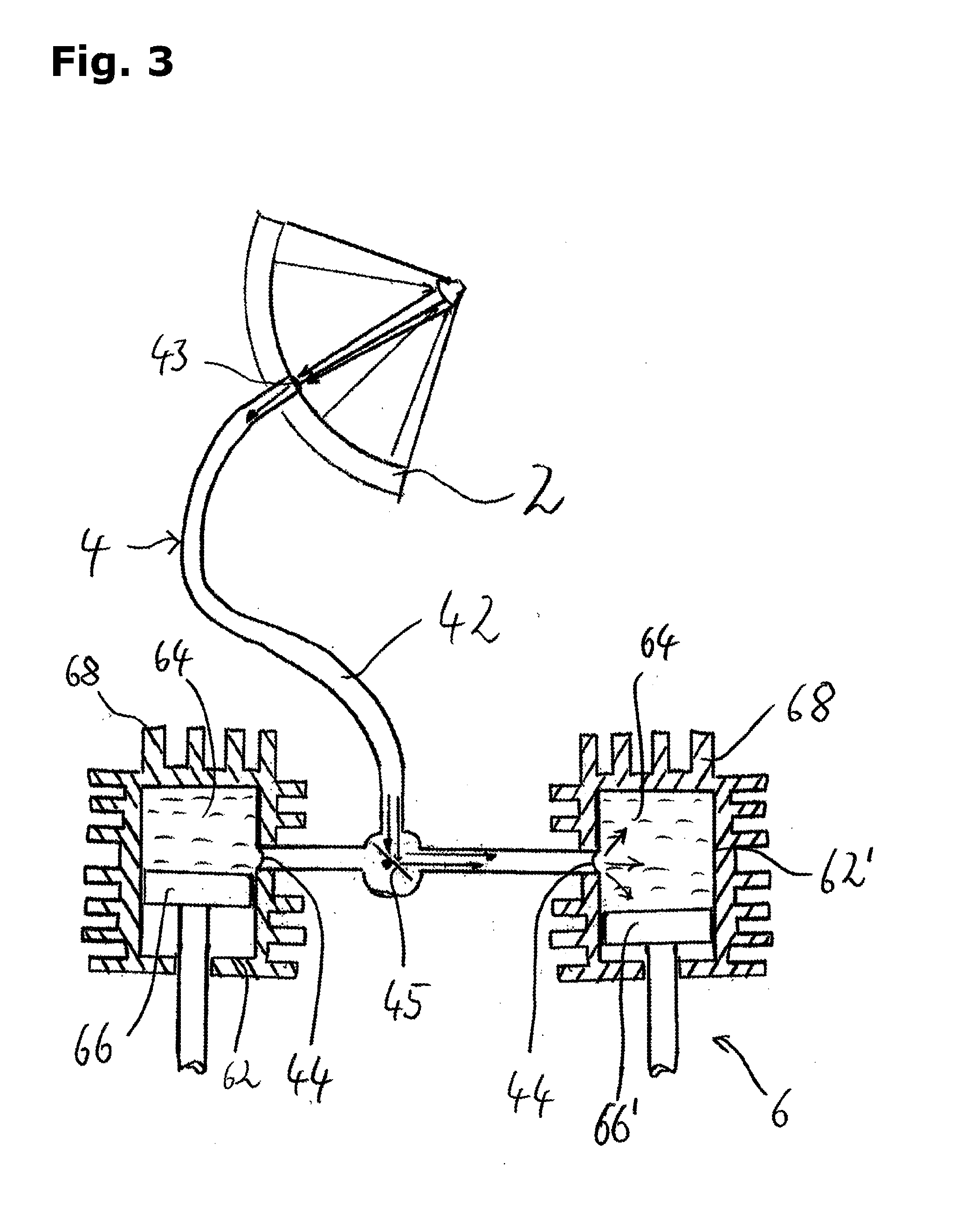
[0021]The apparatus shown in FIG. 1 comprises a collector unit 2, collecting radiation and focusing it to a transfer unit 4, whereby said transfer unit 4 has a second end 44, which is integrated into the inner wall of a first working fluid reservoir 62. Said first working fluid reservoir 62 is part of a working unit 6 and contains a working fluid 64. The end face of said second end 44 of the transfer unit 4 comprises an insulating coating 46 preferably capable of reducing the energy loss caused by infrared radiation from inside said first working fluid reservoir 62, respectively said working fluid 64, passing said transfer unit 4 and escaping to the environment. Expediently said insulating coating 46 is transparent to radiation of shorter wavelength than infrared radiation. The second end 44 of said transfer unit 4 is formed as a lens, preferably concave, to disperse said radiation essentially homogeneously within said first working fluid reservoir 62, respectively within said worki...


PUM


Abstract

An apparatus for utilizing radiation is disclosed. The apparatus may comprise a collector unit, a transfer unit and a working unit. The collector unit comprises at least one radiation reflecting surface adapted to focus radiation and to direct said radiation to said transfer unit. The transfer unit may comprise at least one transparent section, which is integrated into a wall of a first working fluid reservoir of said working unit. The first working fluid reservoir may comprise working fluid, wherein said transfer unit is arranged such as to directly transmit radiation to said working fluid to heat said working fluid.

Description

CROSS-REFERENCE TO RELATED APPLICATIONS[0001]This application claims the benefit of German patent application No. 10 2012 212 837.9, filed on Jul. 23, 2012 the contents of which are hereby incorporated by reference in their entirety into the present disclosure.BACKGROUND[0002]This invention relates to an apparatus for utilizing radiation energy.[0003]Several devices for utilizing different kinds of radiation are known from the prior art. Especially devices for transferring solar radiation energy, i.e. sunlight, into usable forms of energy, especially heat energy or electrical power, have experienced a remarkable raise in importance during the last years, even more due to increasing costs for fossil energy sources. Typically a collecting device collects radiation penetrating a certain area and focuses it to an area, where a part of the radiation energy can be transformed, for instance into heat energy. For transferring the heat energy into working media, in particular working fluids,...

Claims


Application Information

Patent Timeline
IPC IPC(8): F03G6/06F24J2/08F24J2/34F24S20/20F24S23/00F24S23/30F24S23/70F24S23/71
CPCF03G6/06F24J2/345F24J2/08F03G6/068Y02E10/46F24S23/71F24S23/70F24S23/79F24S20/20F24S23/12F24S23/30F24S60/30Y02E10/40F03G6/062
Inventor PETKANCHIN, LACHEZAR LAZAROV
Owner BANKWARE
Why Eureka
Try Eureka