Gas sensor
- Summary
- Abstract
- Description
- Claims
- Application Information
AI Technical Summary
Benefits of technology
Problems solved by technology
Method used
Image


Examples
first embodiment
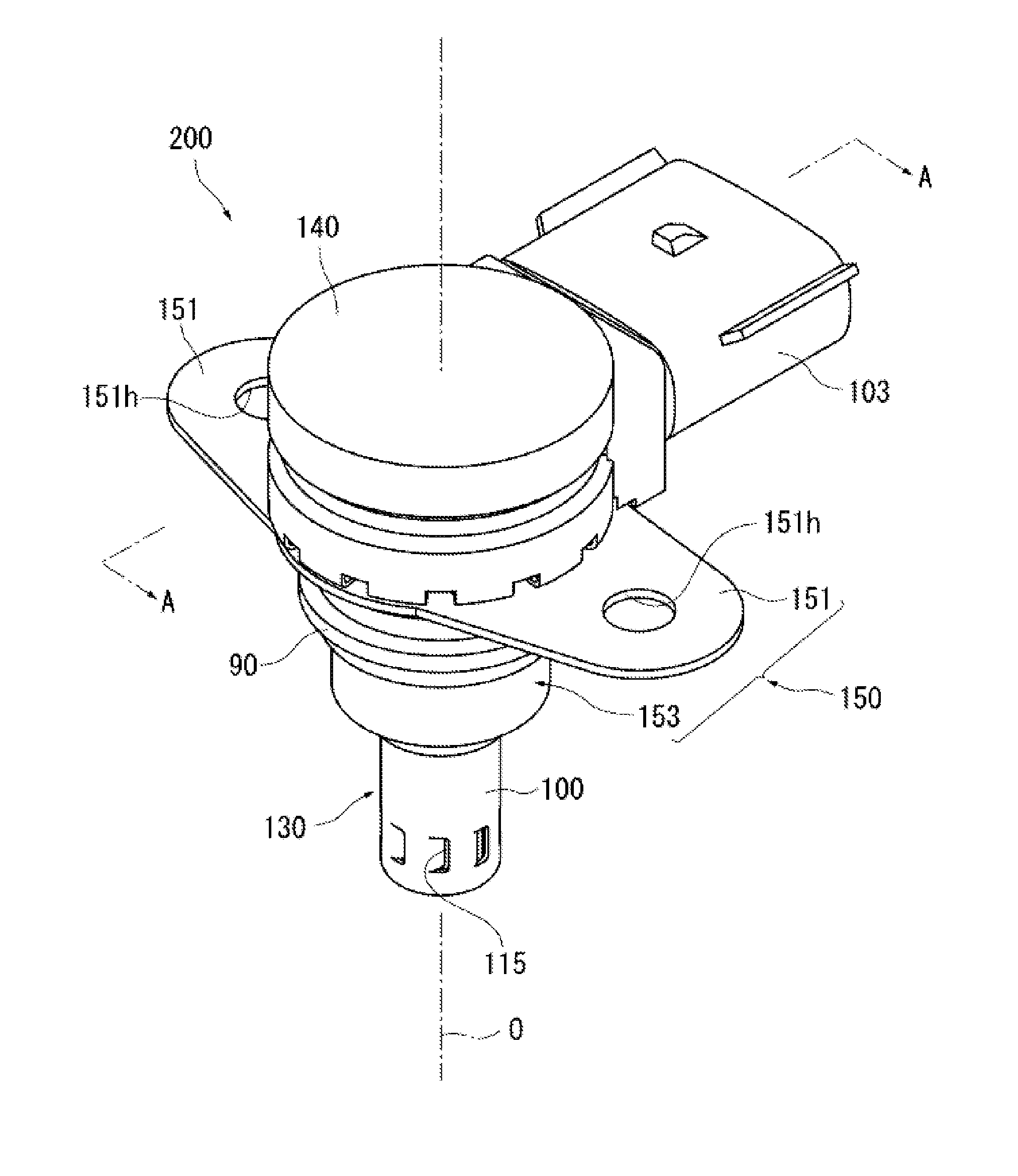
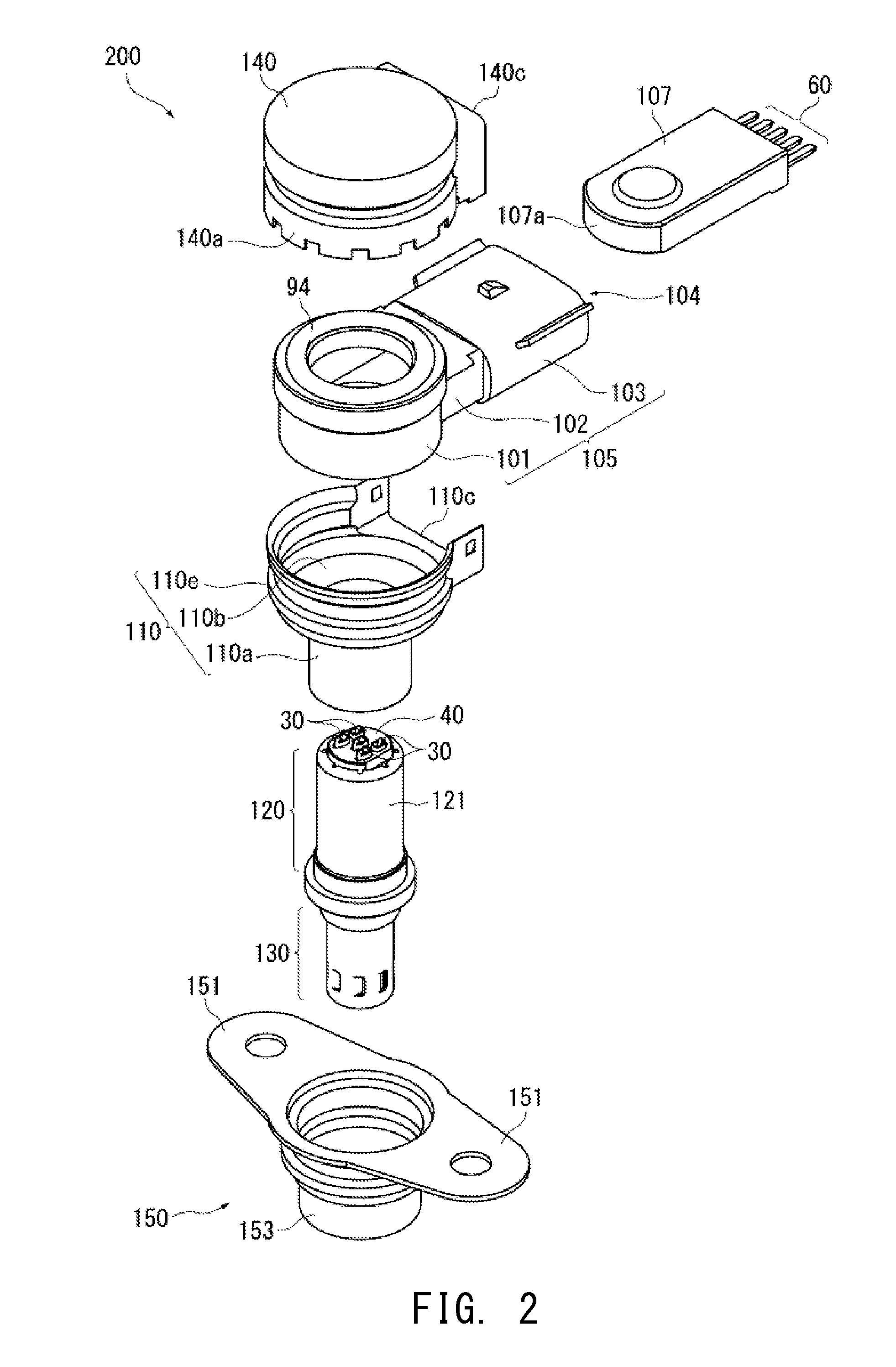
[0075]FIG. 1 is a perspective view of a gas sensor 200 according to the present invention; FIG. 2 is an exploded perspective view of the gas sensor 200; FIG. 3 is a sectional view taken along line A-A of FIG. 1; FIG. 4 is an enlarged perspective view of a connection terminal 30; and FIG. 5 is an enlarged perspective view of a connector terminal 60 and an insulator 107.
[0076]In the drawings, the direction of an axis O (represented by the dash-dot line) of a gas sensor element 10 coincides with the vertical direction. In the following description, a side toward a rear end portion 12 of the gas sensor element 10 is referred to as the rear side of the gas sensor element 10 (and of the gas sensor), and an opposite side toward a detection portion 11 (see FIG. 3) of the gas sensor element 10 is referred to as the forward side of the gas sensor element 10 (and of the gas sensor). A direction perpendicular to the direction of the axis O is referred to as a “radial direction” as appropriate.
[...
second embodiment
[0135]In the second embodiment, the direction in which the elastic portion 331a elastically bends intersects with a direction of juxtaposition of the first connection portion 331 and the second connection portion 361 (radial direction) (i.e., the intersecting direction is the direction of the axis O). Also, the first connection portion 331 is bent radially and is thereby juxtaposed with the second connection portion 361, whereby the first and second connection portions 331 and 361 can be connected.
[0136]Next, with reference to FIGS. 10 and 11, the configuration of a gas sensor 400 according to a third embodiment of the present invention will be described. The gas sensor 400 is similar to the gas sensor of the first embodiment except that the connection terminals 30 and the connector terminals 60 in the first embodiment are replaced with connection terminals 430 and connector terminals 460, respectively. Thus, configurational features similar to those of the first embodiment are deno...
third embodiment
[0143]In the third embodiment, the direction in which the elastic portion 461a elastically bends intersects with a direction of juxtaposition of the first connection portion 431 and the second connection portion 461 (the direction of the axis O). Also, the second connection portion 461 is bent in the direction of the axis O and is thereby juxtaposed with the first connection portion 431, whereby the first and second connection portions 431 and 461 can be connected.
[0144]Next, with reference to FIGS. 12 and 13, the configuration of a gas sensor 500 according to a fourth embodiment of the present invention will be described. The gas sensor 500 is similar to the gas sensor of the second embodiment except that the connection terminals 330 and the connector terminals 360 in the second embodiment are replaced with connection terminals 530 and connector terminals 560, respectively. Thus, configurational features similar to those of the second embodiment are denoted by like reference numera...
PUM
 Abstract
Description
Claims
Application Information
 - R&D
- Intellectual Property
- Life Sciences
- Materials
- Tech Scout
- Unparalleled Data Quality
- Higher Quality Content
- 60% Fewer Hallucinations
Browse by: Latest US Patents, China's latest patents, Technical Efficacy Thesaurus, Application Domain, Technology Topic, Popular Technical Reports.
© 2025 PatSnap. All rights reserved.Legal|Privacy policy|Modern Slavery Act Transparency Statement|Sitemap|About US| Contact US: help@patsnap.com