Removable deployment device, system, and method for implantable prostheses

a deployment device and hernia patch technology, applied in the field of removable deployment devices, systems and methods, can solve the problems of difficult for adept surgeons, cumbersome manual manipulation of the hernia patch, and even greater challenge in manipulating the hernia patch, so as to reduce the effective diameter, reduce the cross-sectional width of the flexible support structure, and reduce the effective diameter

Inactive Publication Date: 2014-01-23
ATRIUM MEDICAL
View PDF7 Cites 51 Cited by
  • Summary
  • Abstract
  • Description
  • Claims
  • Application Information

AI Technical Summary

Benefits of technology

[0024]In accordance with an example embodiment of the present invention, an implantable prosthesis deployment device can include a flexible support structure for removable insertion at least partially within an enclosure of an implantable prosthesis. The flexible support structure can occupy a total circumferential area and can have an elasticity sufficient to generate a force sufficient to cause the prosthesis to assume a deployed configuration when placed in the prosthesis and after being flexed to a non-deployed configuration. A tab can be adjoined with the flexible support structure and can have a length sufficient to extend external to the enclosure when the flexible support structure is in a deployed configuration in the prosthesis. The flexible support structure can be configured in such a way that pulling the tab directionally away from the prosthesis when the flexible support structure is inserted in the prosthesis causes a reconfiguration of the flexible support structure sufficient to enable the flexible support structure to pass through an opening in the prosthesis having a total circumferential area that is less than the total circumferential area occupied by the flexible support structure when the prosthesis is in the deployed configuration, thereby enabling removal of the flexible support structure from the enclosure.
[0025]In accordance with aspects of the present invention, the flexible support structure can include at least one flexible sheet member. The flexible sheet member can include two or more portions that do or do not overlap in a deployed state, depending on the embodiment. The flexible support structure can include a flexible sheet member having one or more slits or openings disposed therethrough. The one or more slits or openings can enable the flexible support structure to reconfigure during removal of the flexible support structure into a different shape having a peripheral edge that delineates a reduced effective diameter. The reconfiguration of the flexible support structure during removal of the flexible support structure can result in a reduced cross-sectional length of the flexible support structure, a reduced cross-sectional width of the flexible support structure, or both. The flexible support structure comprises a flexible framework. The flexible support structure can be configured to apply a generally radially outward force on a radially outermost surface of the enclosure.

Problems solved by technology

However, deploying the hernia patch in this manner is a cumbersome task that requires skillful manual manipulation.
Even then, it is often difficult for an adept surgeon given that such a task is performed under several layers of tissue.
Furthermore, manipulation of the hernia patch can prove to be an even greater challenge in the case of laparoscopic procedures, since trocars used to implant the hernia patch provide limited range of motion, thereby requiring the surgeon to utilize small instruments and graspers.
These absorbable rings or frames tend to lack sufficient strength or can potentially interfere with the intended functionality of the patch, e.g., tissue in-growth or reinforcement.
These patches tend to exhibit greater strength, but consequently may interfere with the functionality of the patch.
For example, permanent rings can form additional contours that can create points of tension at particularly undesirable positions on the surface of the patch.
Still other attempts to facilitate deployment provide a monofilament or wire ring that is crimped or sintered in order to adjoin the ends, which create yet additional weak points that historically have been associated with higher risk of failure, health complications, and even death after implantation.

Method used


Image

  • Removable deployment device, system, and method for implantable prostheses
  • Removable deployment device, system, and method for implantable prostheses
  • Removable deployment device, system, and method for implantable prostheses

Examples


Embodiment Construction

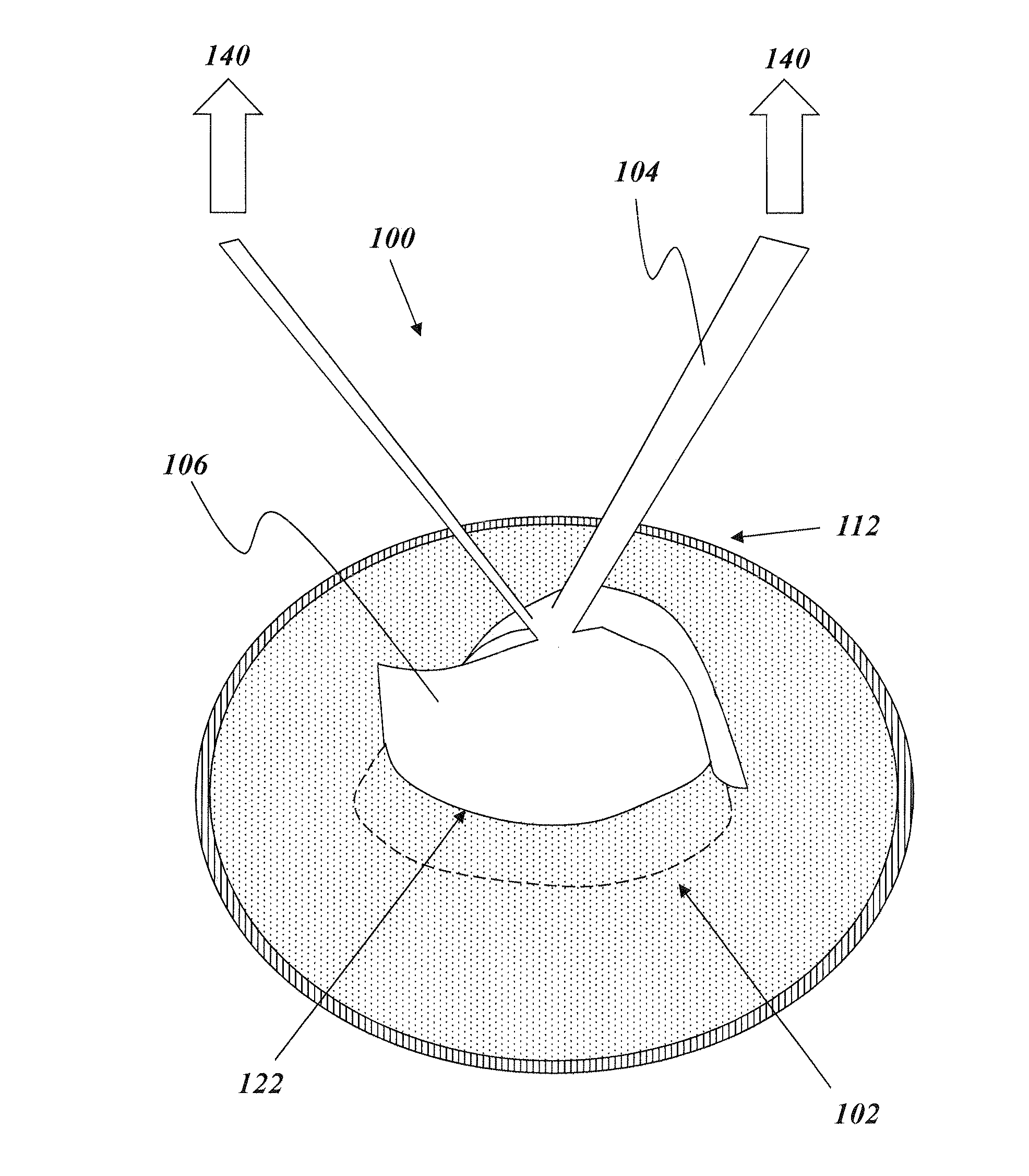
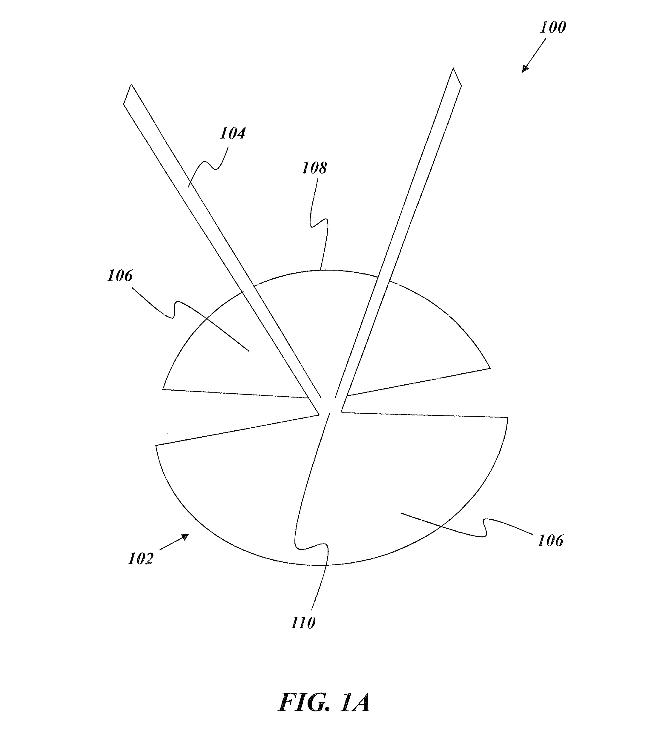
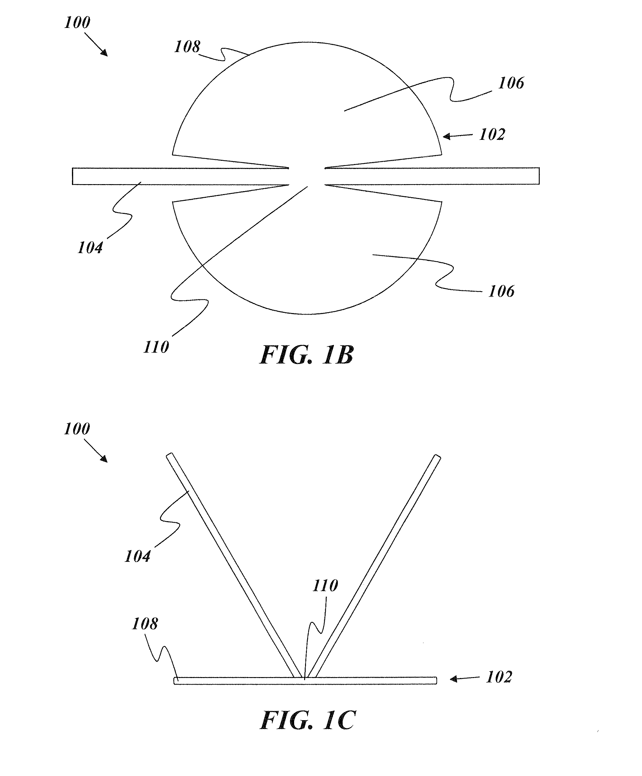
[0091]An illustrative embodiment of the present invention relates to a deployment device capable of deploying a prosthesis, such as a hernia patch, with a more elegant and efficient design than other conventional deployment devices. The deployment device includes a flexible support structure that fits at least partially within an enclosure of the prosthesis, such as one or more pockets in the prosthesis formed by two stacked layers adjoined at a peripheral edge thereof. The flexible support structure has an elasticity that is sufficient to cause the prosthesis to deploy after implantation (e.g., by causing the prosthesis to independently assume a deployed, e.g., generally planar, shape after being implanted in a rolled or otherwise deformed configuration) and a flexibility sufficient to enable bending, folding, or otherwise assuming a collapsed or distorted configuration for removal from the prosthesis. In particular, the flexible support structure can have a flexibility sufficient ...


PUM


Abstract

A prosthesis includes an enclosure. A flexible support structure is situated at least partially within the enclosure and is removable therefrom. The flexible support structure occupies a total circumferential area and has a stiffness that is sufficient to allow the prosthesis to assume a deployed (e.g., generally planar) configuration. A tab is adjoined with the flexible support structure and extends external to the enclosure. Pulling the tab directionally away from the prosthesis causes a reconfiguration of the flexible support structure sufficient to enable the flexible support structure to pass through an opening in the prosthesis having a total circumferential area that is less than the total circumferential area occupied by the flexible support structure when the prosthesis is in the deployed (e.g., generally planar) configuration, enabling removal of the flexible support structure from the enclosure.

Description

RELATED APPLICATION[0001]This application claims priority to, and the benefit of, co-pending U.S. Provisional Application No. 61 / 616,150, filed Mar. 27, 2012, for all subject matter common to both applications. The disclosure of said provisional application is hereby incorporated by reference in its entirety.FIELD OF THE INVENTION[0002]The present invention relates to deployment devices, systems, and methods suitable for medical applications, such as open and laparoscopic ventral hernia repairs and small hernia repair (e.g., repair of umbilical or epigastric defects). More particularly, the present invention relates to a removable deployment device configured to fit within an enclosure of a prosthesis and serve as a surgical aid in the deployment, positioning, and fixation of the prosthesis.BACKGROUND OF THE INVENTION[0003]Prostheses often are implanted during surgical or other medical procedures to aid in repair of defects, reinforcement of a target site, delivery of therapeutic, o...

Claims


Application Information

Patent Timeline
Patent Type & Authority Applications(United States)
IPC IPC(8): A61F2/00
CPCA61F2/0063A61F2/02A61F2002/0072A61F2210/0076A61F2250/0071A61F2230/0091
Inventor HORTON, ANTHONY R.FILIPIAK, DAVIDLEPAGE, JR., ALBERT A.
Owner ATRIUM MEDICAL
Why Eureka
Try Eureka