
Blast load attenuation system for a vehicle

a technology of attenuation system and vehicle, which is applied in the field of structure, can solve the problems of ineffective electronic countermeasures, and increasing the weight of the vehicle,

Active Publication Date: 2014-01-30
THE BOEING CO
View PDF0 Cites 23 Cited by
  • Summary
  • Abstract
  • Description
  • Claims
  • Application Information

AI Technical Summary

Benefits of technology

The present patent describes an apparatus and method for attenuating blast loads in vehicles. The apparatus includes an outer skin, an internal structure, and an inner skin. The internal structure is capable of absorbing energy applied to the outer skin. The internal structure may be connected to the vehicle and may be located between the blast plate and the inner skin. The blast plate may have a curved shape and may be connected to the vehicle. The blast attenuation system can be installed in a vehicle and can attenuate blast loads in the vehicle. The method includes creating a model for the blast plate, running simulations on the model, and manufacturing the blast plate based on the results of the simulations. The technical effects of the patent include reducing the impact of blast loads on vehicles and minimizing damage to infrastructure in the event of a blast.

Problems solved by technology

Improvised explosive devices and / or land mines may target the sides of vehicles and armored vehicles.
These electronic counter-measures, however, may be ineffective against improvised explosive devices that may use trip wires or other non-wireless trigger mechanisms, such as pressure switches used in land mines.
The use of these blast plates, however, may add to the weight of a vehicle.
The weight may reduce the fuel efficiency of a vehicle and increase operating costs.
Further, the weight of currently used blast plates also may increase the strain on other components of the vehicle resulting in more frequent maintenance being needed.
Additionally, the weight of blast plates may reduce the ability of the vehicle to be transported by airplanes and / or helicopters.
The weight of the blast plates also may reduce the acceleration, maneuverability, and / or performance of the vehicle during travel.

Method used


Image

  • Blast load attenuation system for a vehicle
  • Blast load attenuation system for a vehicle
  • Blast load attenuation system for a vehicle

Examples


Embodiment Construction

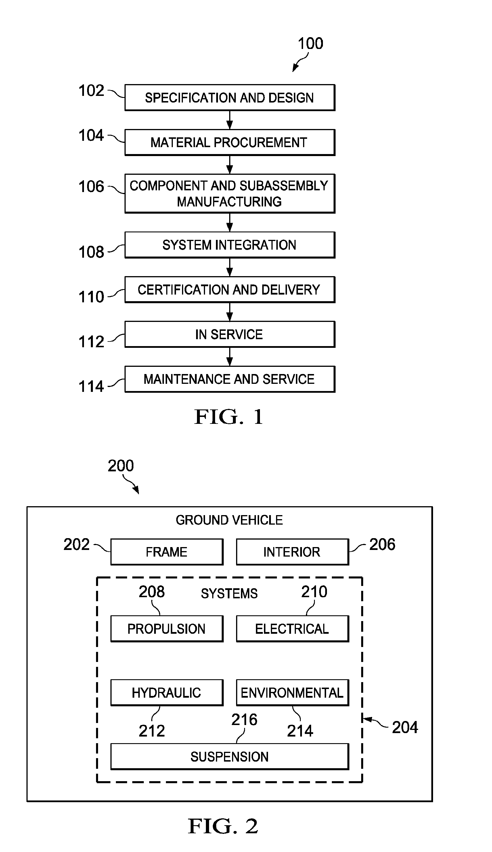
[0039]Referring more particularly to the drawings, embodiments of the disclosure may be described in the context of ground vehicle manufacturing and service method 100 as shown in FIG. 1 and ground vehicle 200 as shown in FIG. 2. Turning first to FIG. 1, an illustration of a ground vehicle manufacturing and service method is depicted in accordance with an advantageous embodiment. During pre-production, exemplary ground vehicle manufacturing and service method 100 may include specification and design 102 of ground vehicle 200 in FIG. 2 and material procurement 104.

[0040]During production, component and subassembly manufacturing 106 and system integration 108 of ground vehicle 200 in FIG. 2 may take place. Thereafter, ground vehicle 200 in FIG. 2 may go through certification and delivery 110 in order to be placed in service 112. While in service by a customer, ground vehicle 200 in FIG. 2 may be scheduled for routine maintenance and service 114, which may include modification, reconfi...


PUM


Abstract

An apparatus may comprise an outer skin having an exterior side and an interior side, an internal structure positioned relative to the interior side of the outer skin, and an inner skin. The internal structure may be capable of absorbing a blast load applied to the exterior side of the outer skin. The internal structure may be located between the outer skin and the inner skin.

Description

BACKGROUND INFORMATION[0001]1. Field[0002]The present disclosure relates generally to a structure and, in particular, a structure that may be used to protect an interior volume from an explosive blast. Still more particularly, the present disclosure relates to a blast attenuation system that may attenuate loads generated by a blast occurring under a vehicle.[0003]2. Background[0004]Improvised explosive devices may be bombs fabricated in an improvised manner. These devices may incorporate explosive materials, as well as fragmentation materials. Improvised explosive devices may be remote controlled and / or triggered by infrared detectors, pressure bars, trip wires, and / or other suitable devices. Mines may be explosive devices placed on or in the ground. When in the ground, these mines may be referred to as land mines. These types of mines may be triggered by an operator and / or the proximity of a vehicle, person, animal, and / or some other suitable object. Improvised explosive devices ma...

Claims


Application Information

Patent Timeline
Patent Type & Authority Applications(United States)
IPC IPC(8): F41H7/04
CPCF41H7/042
Inventor DUNNE, JR., JOHN C.GABRYS, JONATHAN W.LEE, TIMOTHY J.BOYER, ALEXANDER M.CHARLAND, JON C.JEPSON, LARRY
Owner THE BOEING CO
Learn More