Fuel tank fueling device

a fuel tank and fueling technology, applied in the direction of liquid handling, packaging goods, transportation and packaging, etc., can solve the problem and achieve the effect of reducing flow path resistan

Inactive Publication Date: 2014-01-30
TOYODA GOSEI CO LTD +1
View PDF3 Cites 10 Cited by
  • Summary
  • Abstract
  • Description
  • Claims
  • Application Information

AI Technical Summary

Benefits of technology

[0006]The grating member noted in the publication described above is equipped with a plurality of annular bodies arranged in concentric circle form in the fuel path of the inlet pipe, and support members for supporting the annular b

Problems solved by technology

The grating member prevents insertion of a pipe for st

Method used


Image

  • Fuel tank fueling device
  • Fuel tank fueling device
  • Fuel tank fueling device

Examples


first embodiment

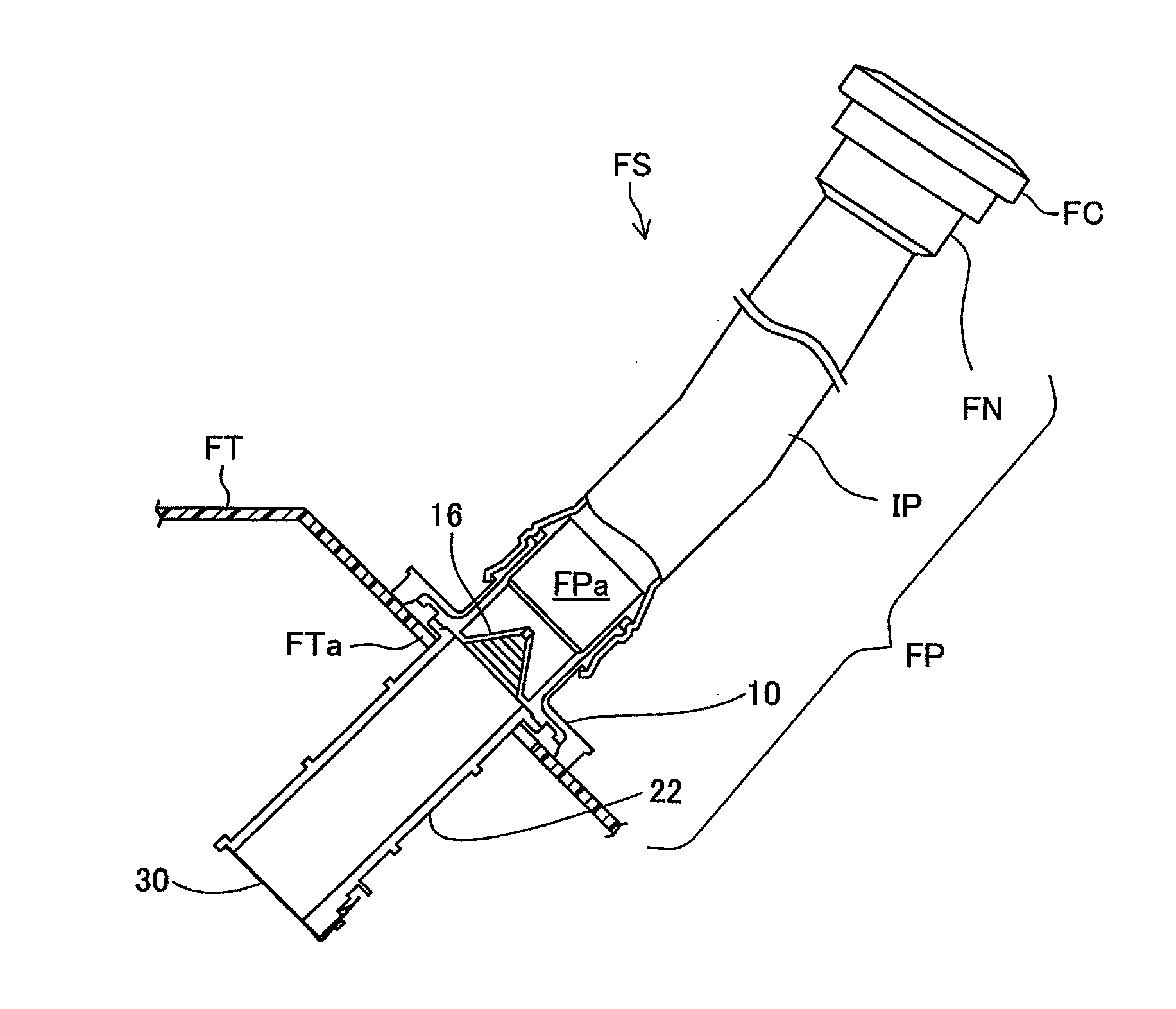
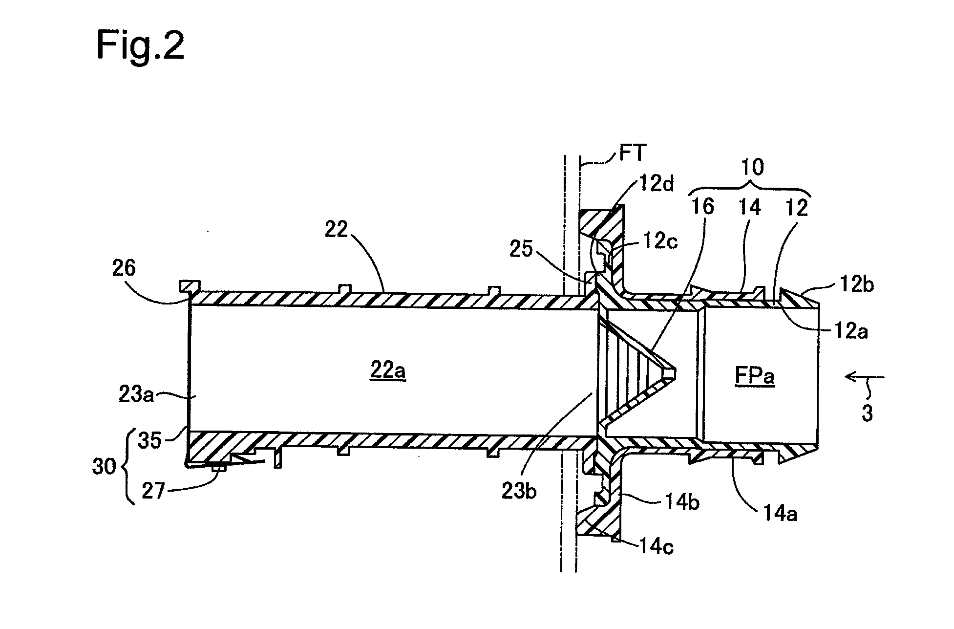
[0035]FIG. 1 is a schematic drawing showing a fueling device FS for supplying fuel to the fuel tank FT of an automobile of the present invention. As shown in FIG. 1, the fueling device FS is connected to the fuel tank FT and sends fuel supplied from a fueling gun (not illustrated) to the fuel tank FT. The fueling device FS is equipped with a fueling pipe FP that forms a fuel path FPa from a fueling port to the fuel tank FT. The fueling pipe FP is equipped with a filler neck FN having the fueling port that is opened and closed by a fuel cap FC, a resin inlet pipe IP connected to one end of the filler neck FN, a fuel tank connector 10 connected to one end of the inlet pipe IP and welded to the fuel tank FT, and a path forming member 22 welded to the fuel tank connector 10. A check valve 30 is mounted on the tip of the path forming member 22. A breather pipe (not illustrated) is connected to the filler neck FN. The breather pipe is connected to the filler neck FN and the fuel tank FT. ...

second embodiment

[0059](4)-1 FIG. 14 is a half section view showing the fuel tank connector 10B of the This embodiment has its characteristic feature in the cross section shape of the partition members 17B of the grating member 16B of the fuel tank connector 10B. The second partition member 17Bb is constituted by an outer surface 17Bb1, an inner circumference wall 17Bb2, and a bottom surface 17Bb3, and is a cross section triangle shape which is one example of the cross section projecting shape. The inner circumference wall 17Bb2 is arranged in parallel with the center line CL. The outer surface 17Bb1 faces toward the bottom edge of the inner circumference wall 17Bb2 from the top edge of the inner circumference wall 17Bb2, and is formed so as to face the center line CL side after curving to the outer circumference side.

[0060]With the shape of the second partition member 17Bb, the inner circumference wall 17Bb2 is formed in parallel with the center line CL, so it is possible for fuel to flow smoothly...

fourth embodiment

[0063]FIG. 16 is a cross section view showing the fuel tank connector 10D of the With this embodiment, the vertex of the triangular cone of the grating member 16D is arranged at the fuel tank side. In this way, it is possible for the arrangement of the partition members of the grating member to use various arrangements taking into consideration the flow path resistance and the manufacturing process.


PUM

PropertyMeasurementUnit
Angleaaaaaaaaaa
Diameteraaaaaaaaaa
Widthaaaaaaaaaa

Abstract

A fueling device is equipped with a grating member provided in a fuel path of a fueling pipe, wherein the grating member is equipped with a plurality of ring shaped partition members arranged in concentric circles with the center line of the fuel path as the center, and having differing diameters, and support members for supporting the partition members in relation to the inner wall of the fueling pipe, and wherein the gaps formed between the inner wall of the fueling pipe, the partition members, and the support members are used as a plurality of gap flow paths which are a portion of the fuel path, and the center of each of the partition members is arranged at different positions on the center line.

Description

[0001]This application claims the benefit of and priority from Japanese Application No. 2012-168296 filed Jul. 24, 2012, the content of which is incorporated herein by reference.BACKGROUND OF THE INVENTION[0002]1. Field of the Invention[0003]The present invention relates to a fueling device for supplying fuel to the fuel tank of a vehicle.[0004]2. Description of the Related Art[0005]An anti-theft mechanism incorporated in the fueling device is disclosed in JP 2010-6246A. The anti-theft mechanism is equipped with a grating member in the fuel path of the inlet pipe to prevent fuel from being stolen through a thin pipe inserted in the inlet pipe from the fuel tank. The anti-theft mechanism is required by law in some cases with vehicles that incorporate engines that use fuel with alcohol content of 20% or greater.SUMMARY[0006]The grating member noted in the publication described above is equipped with a plurality of annular bodies arranged in concentric circle form in the fuel path of t...

Claims


Application Information

Patent Timeline
IPC IPC(8): B60K15/01
CPCB60K15/01B60K2015/03434B60K15/0403
Inventor KANEKO, KENICHIROSEKI, TOSHINORIKITAGAWA, KUNJISHIMOKAWA, SHINJI
Owner TOYODA GOSEI CO LTD
Why Eureka
Try Eureka