Unlock instant, AI-driven research and patent intelligence for your innovation.

Image enhancement system and method

a technology of image enhancement and enhancement system, applied in image enhancement, image analysis, instruments, etc., can solve the problems of black image quality reduction and viewers' annoyance, and achieve the effects of enhancing image quality, reducing overshoot or undershoot, and increasing image quality

Inactive Publication Date: 2014-01-30
HIMAX MEDIA SOLUTIONS +1
View PDF5 Cites 2 Cited by
  • Summary
  • Abstract
  • Description
  • Claims
  • Application Information

AI Technical Summary

Benefits of technology

The present invention provides an image enhancement system and method that improves image quality by reducing overexposure or underexposure while enhancing the image. The system includes a high-pass filter, an adder, and an over-enhancement detection unit. The high-pass filter filters high-frequency spatial components of the input image to produce a high-pass image. The adder adds the high-pass image to the input image to create an enhanced image. The over-enhancement detection unit detects the tendency of the input image towards overexposure or underexposure and uses the output from this detection to prevent overexposure or underexposure in the enhanced image.

Problems solved by technology

The enhanced image with highlighted white or black has reduced image quality and may even annoy viewers.

Method used


Image

  • Image enhancement system and method
  • Image enhancement system and method
  • Image enhancement system and method

Examples


first embodiment

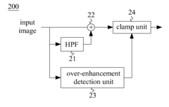
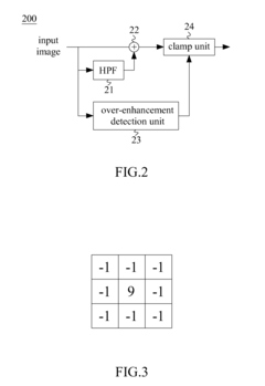
[0017]FIG. 2 shows a block diagram illustrating an image enhancing system 200 according to the present invention. The illustrated system 200 is capable of enhancing an image without incurring over-enhancement (i.e., overshoot or undershoot).

[0018]In the embodiment, the image enhancing system 200 includes a high-pass filter (HPF) 21 that passes high-frequency spatial components of an input image higher than a predetermined cutoff frequency but attenuates low-frequency spatial components. FIG. 3 shows an exemplary high-pass mask (or a sliding window) composed of a 9 at a center and −1s at other locations. The high-pass mask is placed over pixels of the sliding window having a size the same as the high-pass mask, and the pixels are multiplied, by coefficients of the high-pass mask to obtain multiplicands that are then summed up. A high-pass image is accordingly generated from the high-pass filter 21, and is then fed to an adder 22. The adder 22 adds the high-pass image to the input ima...

second embodiment

[0021]FIG. 5 shows a block diagram illustrating an image enhancing system 500 according to the present invention. The present embodiment is similar to the first embodiment (FIG. 2) except for the following differences. In the embodiment, a multiplier 25 is used, rather than the clamp unit 24, to adjust the high-pass image (instead of the enhanced image) when the over-sum or the under-sum (from the over-enhancement detection unit 23) indicates that overshoot or undershoot may occur. Specifically, the high-pass image is multiplied (by the multiplier 25) by a scale value that depends on the over-sum or the under-sum. Generally speaking, the less the over-sum or the under-sum is, the greater the scale value is.

[0022]FIG. 6 shows a block diagram illustrating an image enhancing system 600 according to a third embodiment of the present invention. The present embodiment adopts both schemes used in the first embodiment (FIG. 2) and the second embodiment (FIG. 5). In other words, the clamp un...


PUM


Abstract

An image enhancement system and method include a high-pass filter (HPF) configured to pass high-frequency spatial components of an input image to generate a high-pass image; an adder configured to add the high-pass image to the input image, thereby resulting in an enhanced image; and an over-enhancement detection unit configured to detect tendency of the input image towards overshoot or undershoot. An output of the over-enhancement detection unit is used to prevent overshoot or undershoot in the enhanced image.

Description

BACKGROUND OF THE INVENTION[0001]1. Field of the Invention[0002]The present invention generally relates to an image enhancing system and method, and more particularly to an image enhancing system and method being capable of enhancing an image without incurring over-enhancement.[0003]2. Description of Related Art[0004]An image may commonly be subjected to enhancement by image processing technique, for example, to increase contrast or detect edge. For example, high-frequency spatial components of an original image are first extracted, and are then added to the original image to obtain an enhanced image. FIG. 1A schematically shows a waveform of an original signal, and FIG. 1B schematically shows a waveform of an extracted signal. When the extracted signal (FIG. 1B) is added to the original signal (FIG. 1A), a resultant enhanced signal as shown in FIG. 1C may be obtained. However, overshoot or undershoot may ordinarily occur in the enhanced signal as exemplified in FIG. 1C, which appea...

Claims


Application Information

Patent Timeline
IPC IPC(8): G06T5/00
CPCG06T5/003G06T2207/20192G06T5/75G06T5/73
Inventor CHEN, TSUI-CHINTSAI, CHIN-JUNG
Owner HIMAX MEDIA SOLUTIONS