Footwear article with pressure sensor

a technology of pressure sensor and footwear, applied in the field of footwear articles, to achieve the effect of flexible adjustmen

Inactive Publication Date: 2014-02-06
IEE INT ELECTRONICS & ENG SA
View PDF3 Cites 66 Cited by
  • Summary
  • Abstract
  • Description
  • Claims
  • Application Information

AI Technical Summary

Benefits of technology

[0003]The disclosure provides an article of footwear including a pressure sensor, wherein the r...

Problems solved by technology

If another resistance vs. pressure characteristic is needed, a su...

Method used


Image

  • Footwear article with pressure sensor
  • Footwear article with pressure sensor
  • Footwear article with pressure sensor

Examples


Embodiment Construction

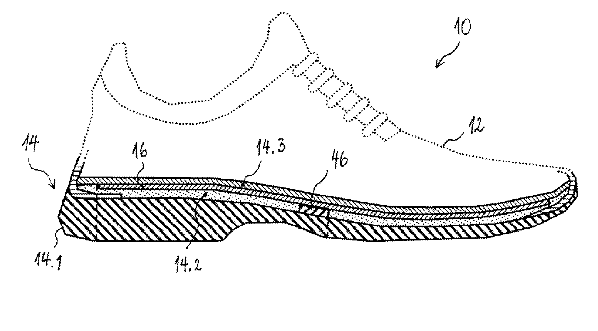
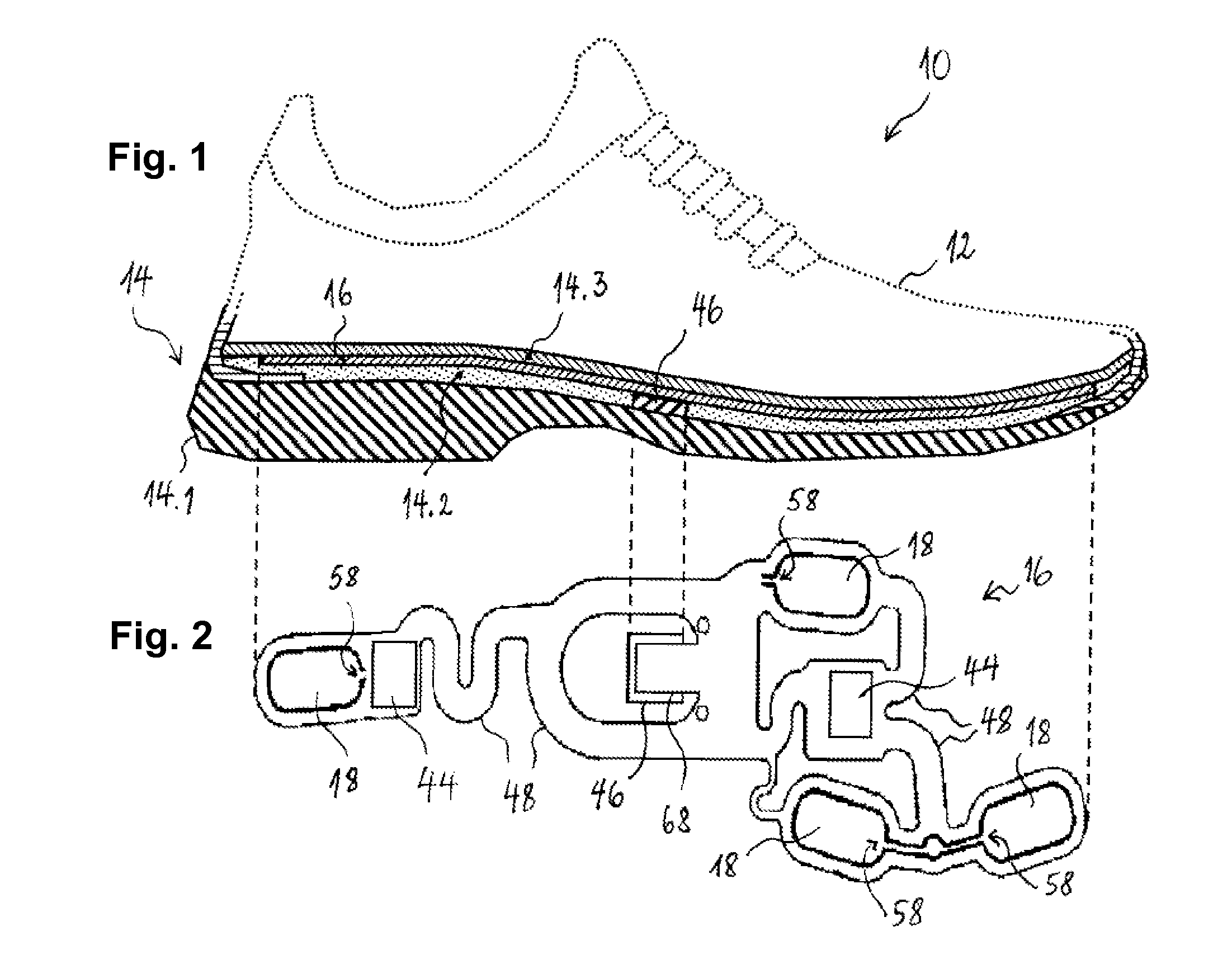
[0031]An article of footwear, in form of a sports shoe 10 is depicted in FIG. 1 as including an upper 12 and a sole structure 14. The upper 12 is secured to sole structure 14 and defines chamber for receiving a foot. The sole structure 14 includes an outsole 14.1, a midsole 14.2, and an insole 14.3, which forms the bottom of the foot-receiving chamber of the sport shoe 10.

[0032]In the illustrated embodiment, the midsole 14.2, which is preferably formed of impact-attenuating material, has a film-type pressure sensor 16 attached to its upper surface. When the insole is in place, the pressure sensor 10 is thus sandwiched between the insole 14.3 and the midsole 14.2.

[0033]As best shown in FIG. 2, the pressure sensor 16 comprises a plurality of pressure-sensing cells 18, located in different areas of the sole structure 14, for measuring pressure exerted by the wearer's foot on the sole structure 14.

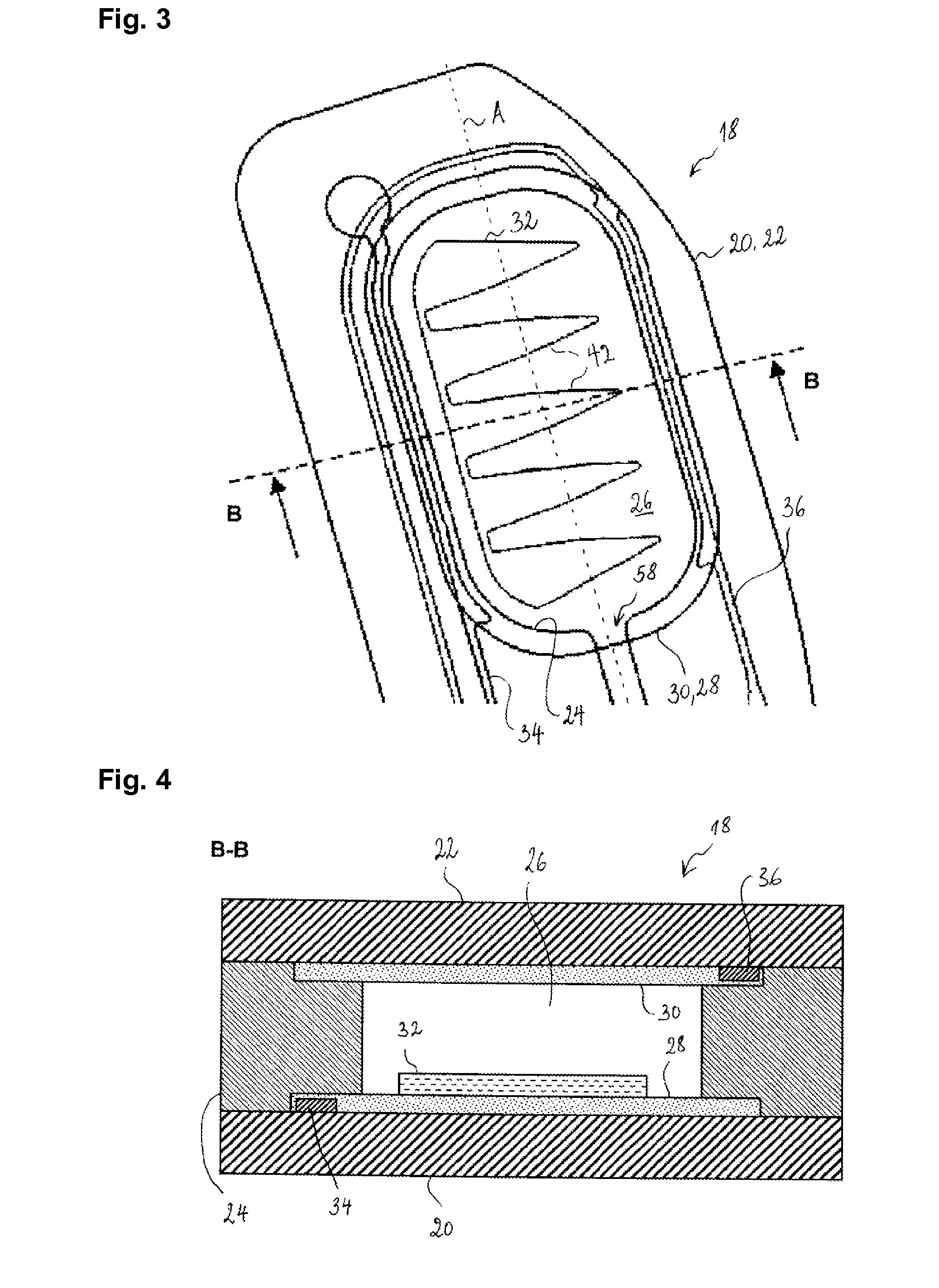
[0034]The configuration of the pressure sensing cells 18 will now be described with refere...


PUM


Abstract

An article of footwear including a pressure sensor arranged in the sole structure, where the sensor includes elongated pressure-sensing cells, each of which has an axis of main extension, each cell having a first and a second carrier film, which are attached to one another by a spacer film having an elongated opening oriented along the axis of main extension, as well as a first and a second electrode on the first and the second carrier film, respectively, where the electrodes are arranged in facing relationship with each other, so that a contact area between them increases with increasing pressure, and an electrically insulating layer is arranged within the opening having a shape such that it locally prevents direct contact between the electrodes where the insulating layer is present and enables the direct contact where it is absent, where the shape is constant or repetitionary along the axis of main extension of the cell.

Description

TECHNICAL FIELD[0001]The present invention generally relates to an article of footwear, such as e.g. a shoe, a boot, a sandal or the like, in particular an article of footwear equipped with a pressure sensor for measuring pressure exerted by the wearer's foot on the sole structure.BACKGROUND ART[0002]Document U.S. 2010 / 0063779 discloses a shoe with an integrated sensor system. The sensor system collects performance data that are transferred for further use via a communication port. The shoe contains a force sensor arranged in the sole structure for measuring, in a plurality of areas, pressure (force) exerted by the wearer's foot on the sole structure, and an electronic module configured to gather data from the sensors. The module is configured for transmitting the data to an external device for further processing. In one of the embodiments disclosed in U.S. 2010 / 0063779, the pressure sensor comprises four elongated pressure-sensing cells, each of which contains a first and a second ...

Claims


Application Information

Patent Timeline
IPC IPC(8): A43B7/00
CPCA43B7/00A43B7/08A61B5/1038A63B2220/56A63B2220/58A63B2220/836A63B2225/50A63B2230/62G01L1/205A43B3/34
Inventor STEIER, ANDREASKIRSCH, ALOYSEMASSING, MATHIAS
Owner IEE INT ELECTRONICS & ENG SA
Why Eureka
Try Eureka