Mortise Lock Apparatus and Electronic Operating System

a technology of electronic operating system and mortise lock, which is applied in the direction of mechanical equipment, fastening means, manufacturing tools, etc., can solve the problems of exterior fasteners detracting from the aesthetics of the door, difficult installation of traditional mortise lock systems, and problems with alignment and smooth function

Active Publication Date: 2014-02-06
BELWITH PROD
View PDF23 Cites 41 Cited by
  • Summary
  • Abstract
  • Description
  • Claims
  • Application Information

AI Technical Summary

Benefits of technology

[0008]In another aspect, the disclosure describes a locking system for a door including a mortise pocket. The locking system includes a mortise case adapted for disposal within the mortise pocket. The mortise case defines an alignment hole. The locking system also has a gear box and a worm gear disposed within the gear box. The worm gear defines a notched passage that receives a lock knob shaft. A worm within the gear box is coupled to a motor capable of rotating the worm. The worm engages the worm gear such that the worm gear rotates when the worm rotates. A control board disposed within the gear box receives electronic signals and transmits electronic signals to the motor to cause the motor to rotate the worm. The gear box also has a worm gear hub that defines a keyed passage and a hub tab. The worm gear hub is adapted for disposal in the notched passage of the worm gear and the keyed passage is shaped receive the lock knob shaft. The worm gear also has two notches that define the notched passage and the hub tab is adapted to contact the notches individually when the gear hub rotates within the keyed passage.
[0009]In another aspect, the disclosure describes a locking system for a door including a mortise pocket. The locking system comprises a mortise case adapted for disposal within the mortise pocket and the mortise case defines an alignment hole. The locking system also includes a gear box that defines at least one depression and at least one disc. The disc is adapted to fit partially into the alignment hole of the mortise case and simultaneously fit partially into the depression to ensure proper alignment between the mortise case and the gear box.

Problems solved by technology

Traditional mortise lock systems are difficult to install and can often have problems with alignment and smooth function.
Exterior fasteners detract from a door's aesthetic and provide intruders with potential entry points in the lock.
Additionally, since part of a door's interior must be removed in order to install a mortise lock, traditional locks leave the door weakened and vulnerable to forced entry.

Method used


Image

  • Mortise Lock Apparatus and Electronic Operating System
  • Mortise Lock Apparatus and Electronic Operating System
  • Mortise Lock Apparatus and Electronic Operating System

Examples


Embodiment Construction

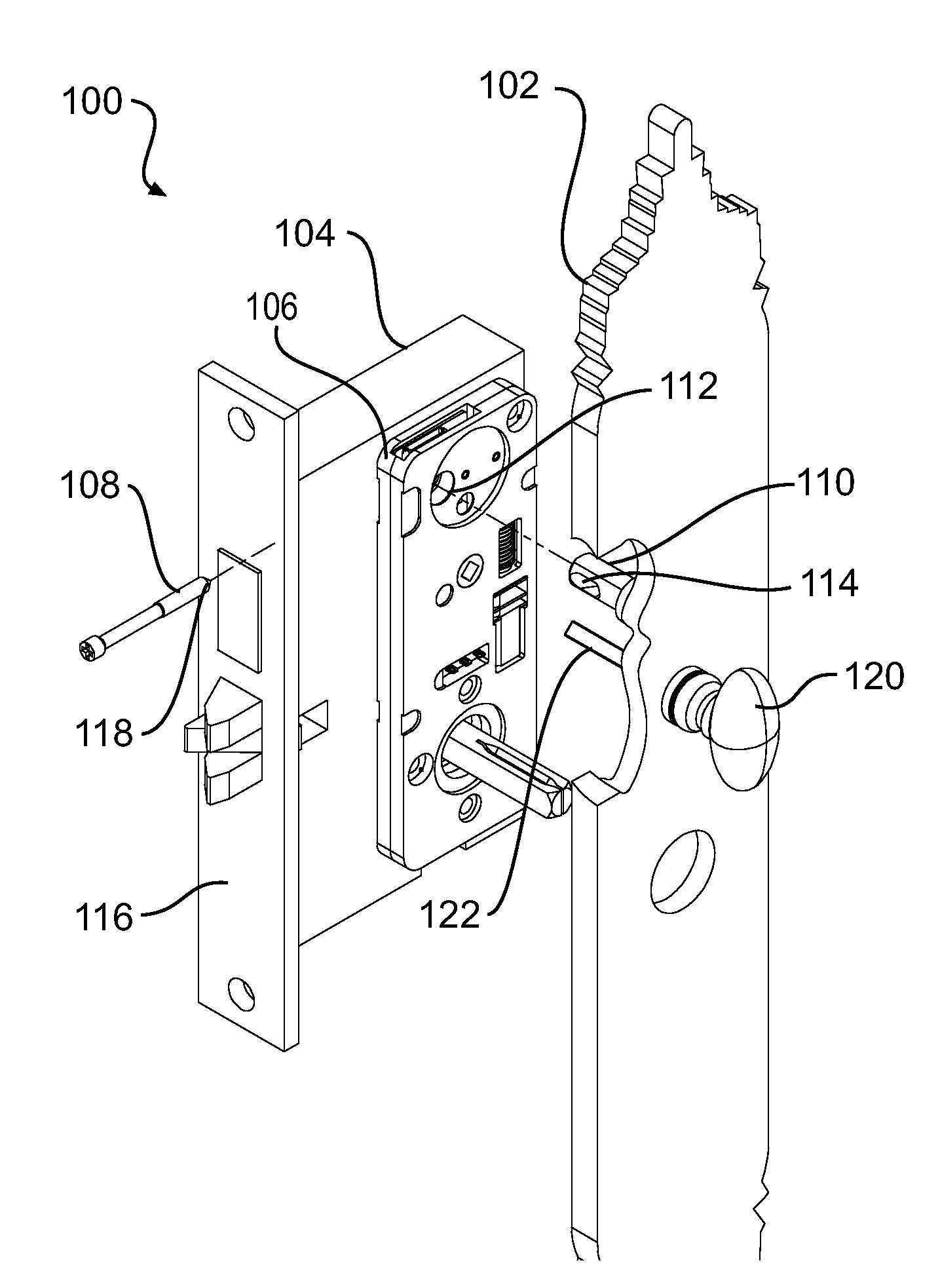
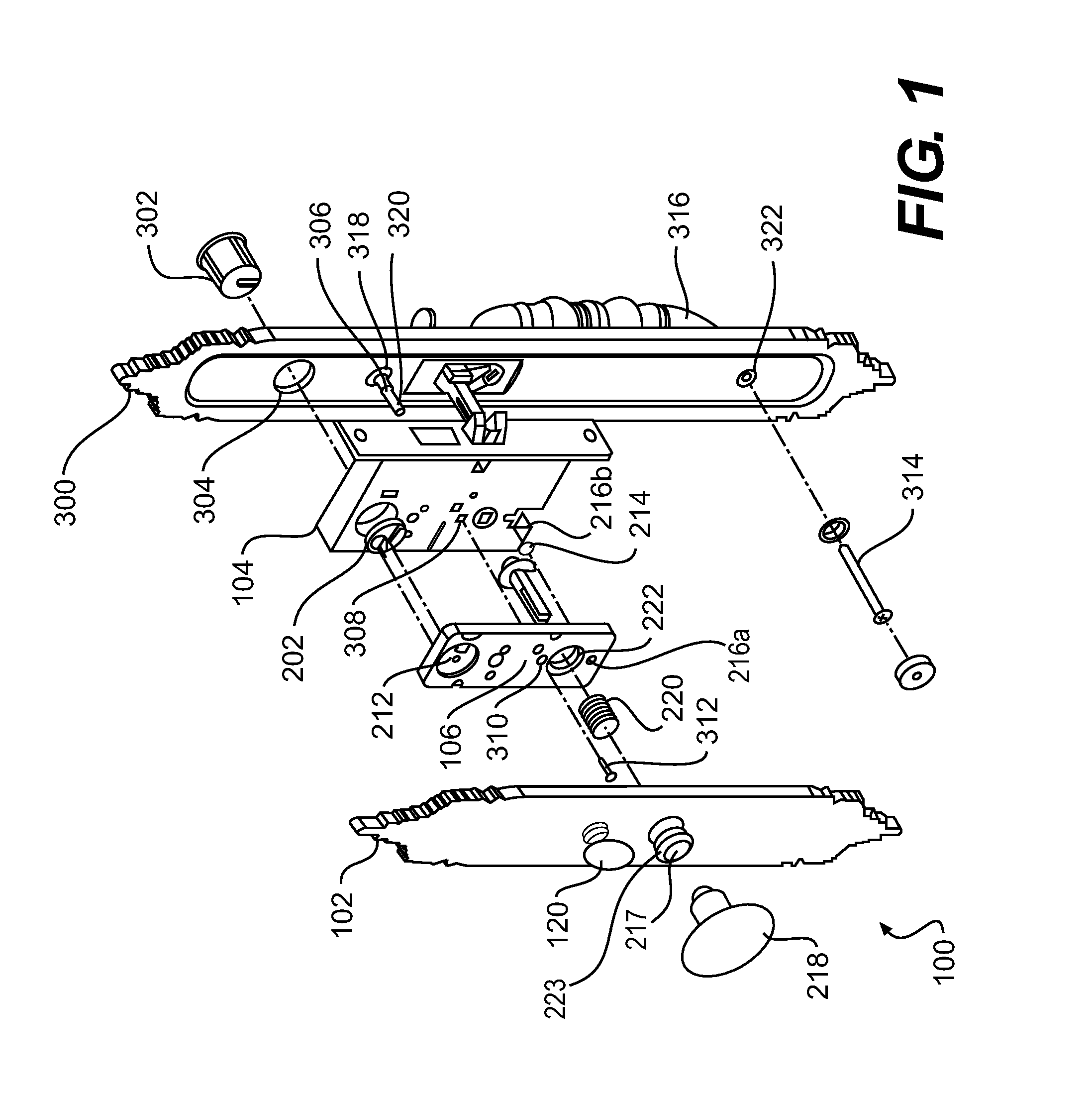
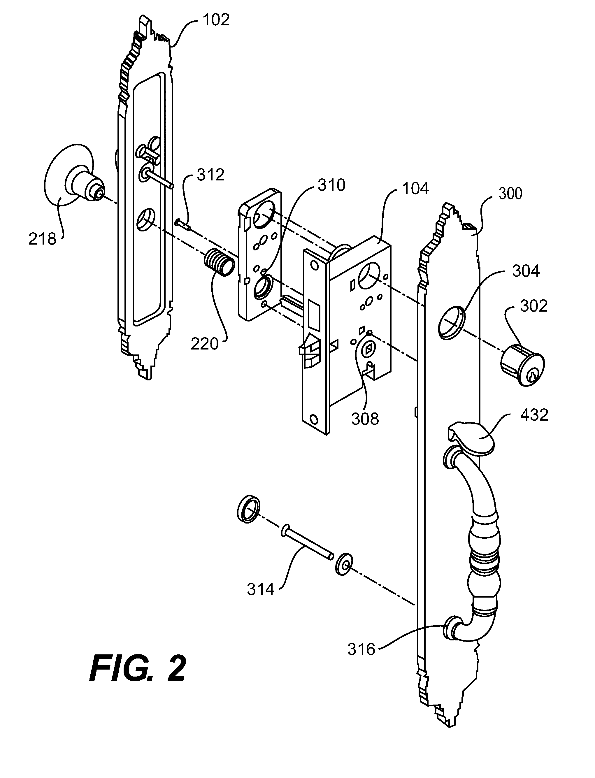
[0079]This disclosure relates to a locking system 100 that can be implemented into various types of doors or entrances. It should be appreciated that, throughout the discussion and corresponding figures, like reference characters refer to like parts. Any suitable combination of various embodiments can be utilized in the locking system 100 as disclosed herein. FIG. 7 and FIG. 8 provide basic illustrations of the disclosed locking system 100. Hidden lines depict features of the locking system 100 hidden from view. The locking system 100 includes a knob 218, a lock knob 120, a dead bolt 130, a latch bolt 132, an inner escutcheon 102, an outer escutcheon 300, and a strike plate 134. The disclosed locking system 100 is installed into a door 126 or any other type of entryway, and can operate either mechanically or electronically. To operate electronically, the locking system 100 has an electromechanical drive that will be detailed further in this disclosure. The gear box 106 and the morti...


PUM

PropertyMeasurementUnit
timeaaaaaaaaaa
areaaaaaaaaaaa
diameteraaaaaaaaaa

Abstract

The disclosure describes a locking system for a door with a mortise pocket. The locking system has a mortise case within the mortise pocket. The mortise case defines an alignment hole. The locking system also has a gear box with a worm gear that defines a notched passage that receives a lock knob shaft. A worm within the gear box is coupled to a motor that rotates the worm. The worm engages the worm gear such that the worm gear rotates when the worm rotates. A control board in the gear box is adapted to receive electronic signals and transmit them to the motor to cause the motor to rotate the worm. The gear box also has a worm gear hub that defines a keyed passage and a hub tab. The worm gear hub fits within the notched passage and the keyed passage receives the lock knob shaft. The worm gear also has two notches that the hub tab contacts individually when the gear hub rotates within the keyed passage.

Description

REFERENCE TO RELATED APPLICATIONS[0001]This application is related to U.S. Application No. 61 / 430,621 (Attorney Docket No. 271152) filed Jan. 16, 2011 entitled “System and Method for Access Control Via Mobile Device,” and U.S. Application No. 61 / 355,303 filed Jun. 16, 2010 entitled “Wireless Device Enabled Locking System,” which are incorporated herein by reference in their entirety for all that they teach.COPYRIGHT NOTICE[0002]A portion of this patent document contains material that is subject to copyright protection. The copyright owner has no objection to the facsimile reproduction by anyone of the patent document, as it appears in the Patent and Trademark Office patent files or records, but otherwise reserves all copyright rights whatsoever.[0003]Cross-reference is also made to applicant / assignee's user's manual, “Keeler® Door Locks with SecuRemote™ Technology User Manual,” which is incorporated herein by reference.FIELD OF THE INVENTION[0004]This invention relates generally to ...

Claims


Application Information

Patent Timeline
Patent Type & Authority Applications(United States)
IPC IPC(8): E05B63/08E05B9/02E05B17/00E05C1/00
CPCE05B63/08E05B17/0004E05B9/02E05C1/004E05B15/02E05B47/0012Y10T29/49947Y10T70/5319Y10T292/62Y10T292/1022Y10T292/1021E05B2047/002E05B9/082E05B2047/0091
Inventor MYERS, GARY L.HIRPARA, ASHOKCOHEN, MICHAEL AARONVELERIS, JOHN D.NELSON, ALYSSA M.
Owner BELWITH PROD
Why Eureka
Try Eureka