
Method and Apparatus for Reducing Radiated Emissions in Switching Power Converters

a technology of switching power converters and radiated emissions, which is applied in the direction of electronic commutators, motor/generator/converter stoppers, dynamo-electric converter control, etc., can solve the problems of radiated emissions, the magnitude of radiated emissions does not necessarily increase, and the size and expense of reducing radiated emissions

Active Publication Date: 2014-02-06
ROCKWELL AUTOMATION TECH
View PDF59 Cites 12 Cited by
  • Summary
  • Abstract
  • Description
  • Claims
  • Application Information

AI Technical Summary

Benefits of technology

This patent describes a device that converts electricity from one form to another for use with motors. It uses filters to reduce harmful signals released during this process. The device contains multiple switches and a large capacity battery which work together to create a smooth motion.

Problems solved by technology

The technical problem addressed in this patent is reducing radiated emissions from motor drives caused by the rapid switching of the output to the DC bus and overshoot and subsequent oscillation as the output voltage settles. The current solutions of adding a ferrite core or a common mode inductor to the output of the motor drive are expensive and require large size, which need to be addressed.

Method used


Image

  • Method and Apparatus for Reducing Radiated Emissions in Switching Power Converters
  • Method and Apparatus for Reducing Radiated Emissions in Switching Power Converters
  • Method and Apparatus for Reducing Radiated Emissions in Switching Power Converters

Examples


Embodiment Construction

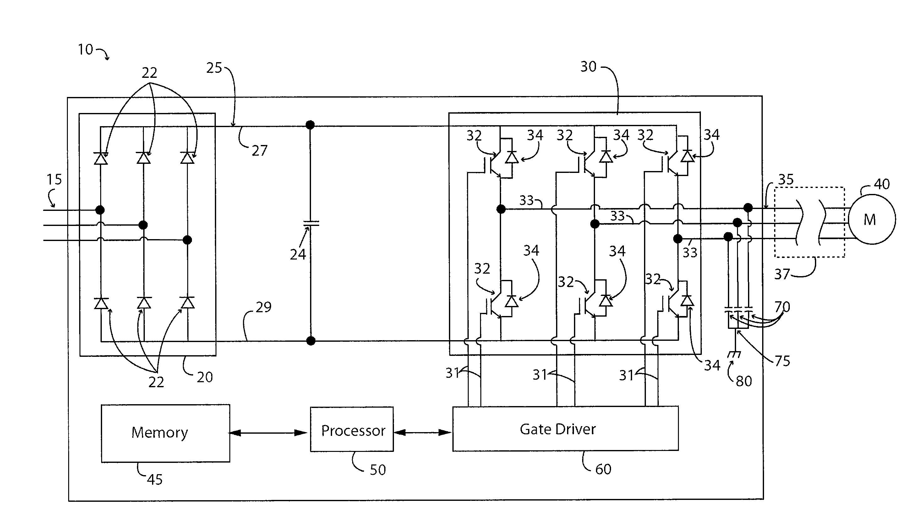
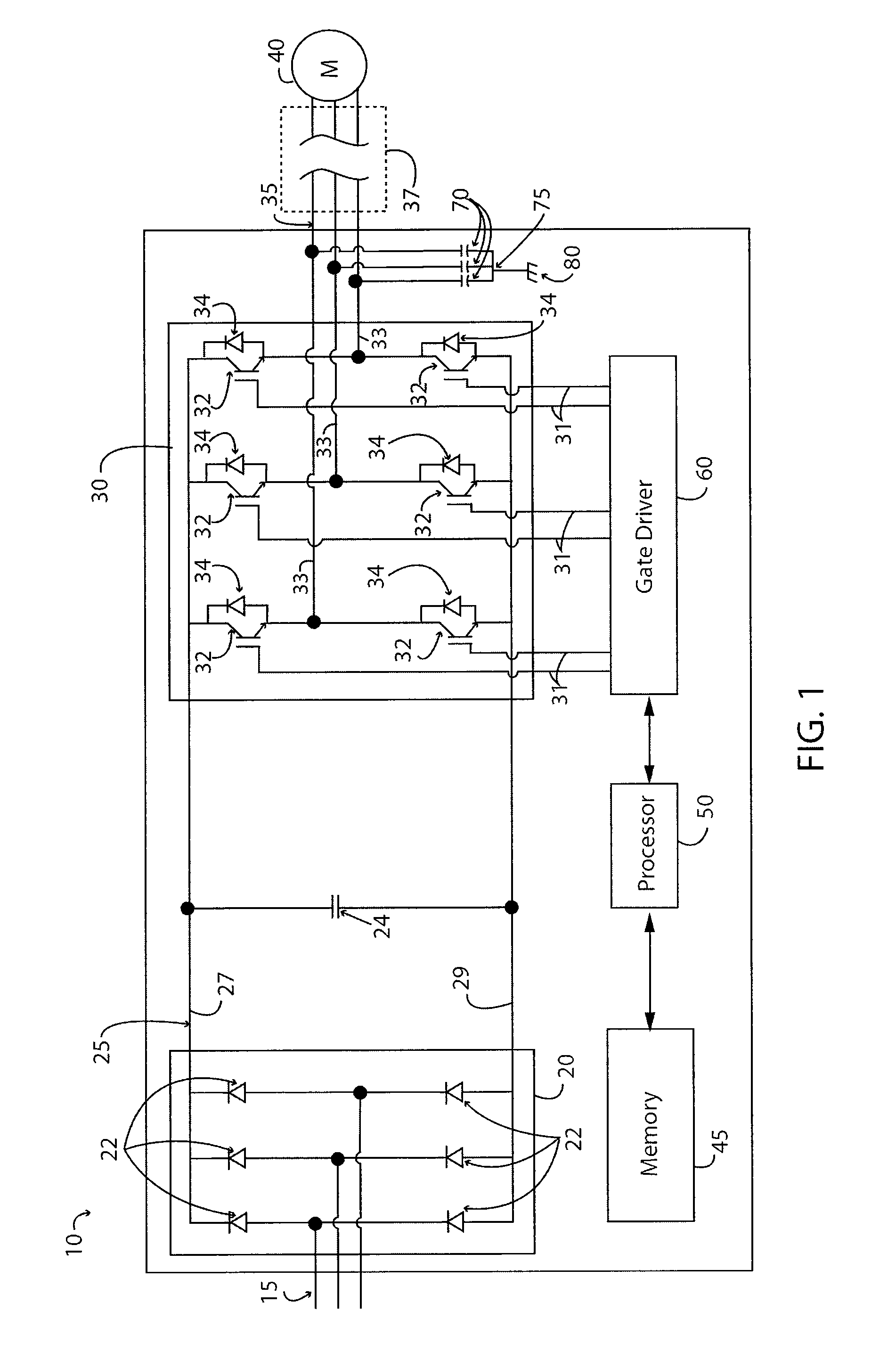
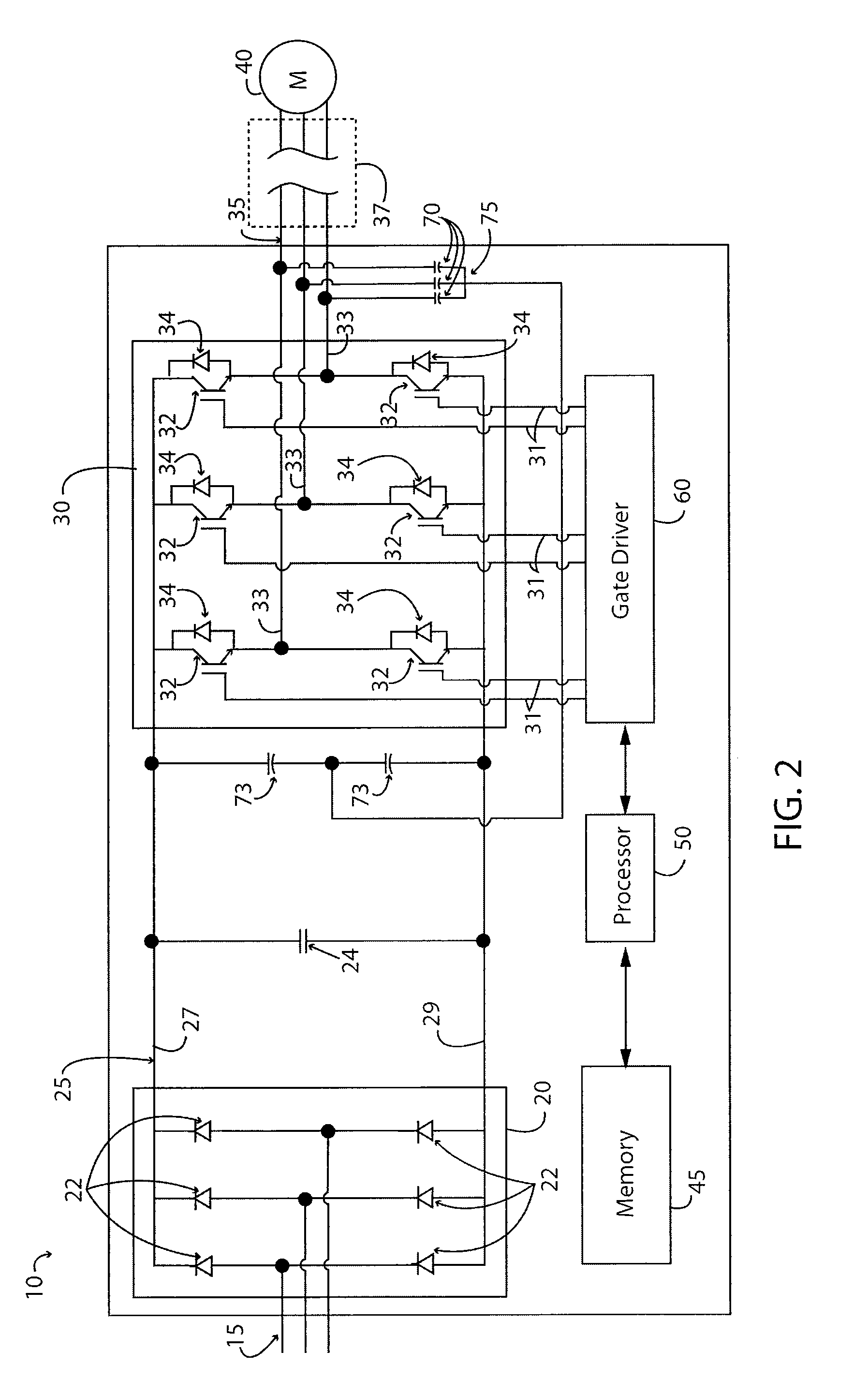
[0024]Turning initially to FIG. 1, a motor drive 10, according to one embodiment of the invention, is configured to receive a three-phase input power 15 at rectifier section 20. The rectifier section 20 may include any electronic device suitable for passive or active rectification as is understood in the art. The illustrated rectifier section 20 includes a set of diodes 22 forming a diode bridge that rectifies the three-phase input power 15 to a DC voltage on the DC bus 25. Optionally, the rectifier section 20 may include other solid state devices including, but not limited to, thyristors, silicon controlled rectifiers (SCRs), or transistors to convert the input power 15 to a DC voltage for the DC bus 25. The DC voltage potential is present between a positive rail 27 and a negative rail 29 of the DC bus 25. A DC bus capacitor 24 is connected between the positive and negative rails, 27 and 29, to reduce the magnitude of the ripple voltage resulting from converting the AC voltage to a...


PUM


Abstract

A filter for reducing radiated emissions in switching power converters such as a motor drive is disclosed. The switching power converter modulates a DC voltage input to generate a desired AC voltage output. Capacitors are connected in parallel between each output phase and a common connection, which may be a ground connection. The magnitude and layout of the capacitors are selected to minimize current conducted by the capacitors. The capacitors may be surface mount technology located proximate to the switching devices or the capacitors may be incorporated in the circuit board on which the switching devices are mounted. The filter may be applied to any of the switching elements in a motor drive, such as the inverter section, an active rectifier section, or a switched mode power supply.

Description


Claims


Application Information

Patent Timeline
Owner ROCKWELL AUTOMATION TECH
Learn More