
Apparatus, an assembly, a vehicle and a method for forming a drainage assembly within and along an elongate trench

a technology of drainage assembly and assembly, which is applied in irrigation ditches, agriculture, construction, etc., can solve the problems of preventing or hindering agriculture, compromising ground stability, and significant damage to roads and buildings, and achieves the effect of easy re-filling and increasing the capacity of the vehicl

Inactive Publication Date: 2014-02-06
DITJET INTPROP PTY
View PDF2 Cites 4 Cited by
  • Summary
  • Abstract
  • Description
  • Claims
  • Application Information

AI Technical Summary

Benefits of technology

The patent describes an apparatus that can quickly and easily create a drain assembly in a trench without requiring a lot of labor. This saves time and money. The apparatus automatically forms the drain assembly, making sure it is consistent along its length. The end of the perforated conduit is fixed in the trench to make sure it is pulled in tightly as the vehicle moves along. Overall, this invention makes it easier and more efficient to create drainage systems.

Problems solved by technology

Waterlogged areas can often cause significant damage to roads and buildings, prevent or hinder agriculture and otherwise compromise the stability of the ground.
As can be appreciated from above, there are many individual steps involved in forming a French drain assembly and it becomes a time consuming and labour intensive process.
This problem is exacerbated when installing extensive networks of drain assemblies, which can extend for hundreds of kilometers.
Furthermore, the quality of the drain assembly is often compromised as it is difficult to install even and consistent amounts of the aggregate material and it is also difficult to maintain the position, depth and orientation of the elongate conduit consistent throughout the length of the drain assembly.

Method used


Image

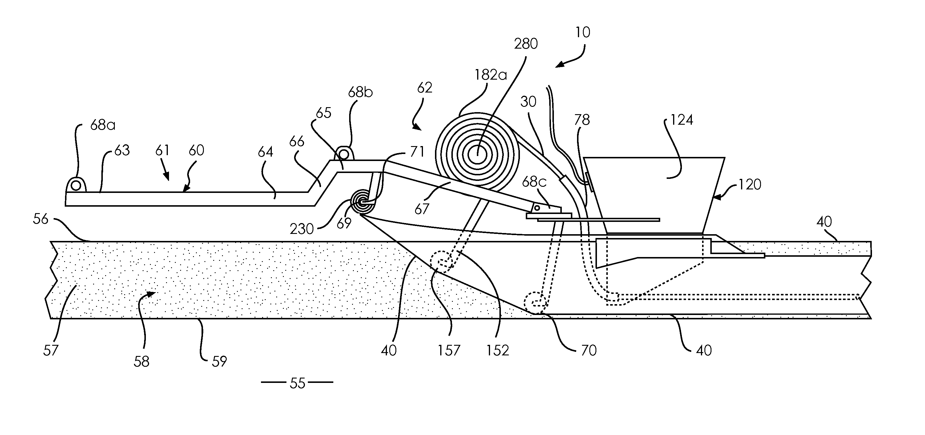
  • Apparatus, an assembly, a vehicle and a method for forming a drainage assembly within and along an elongate trench
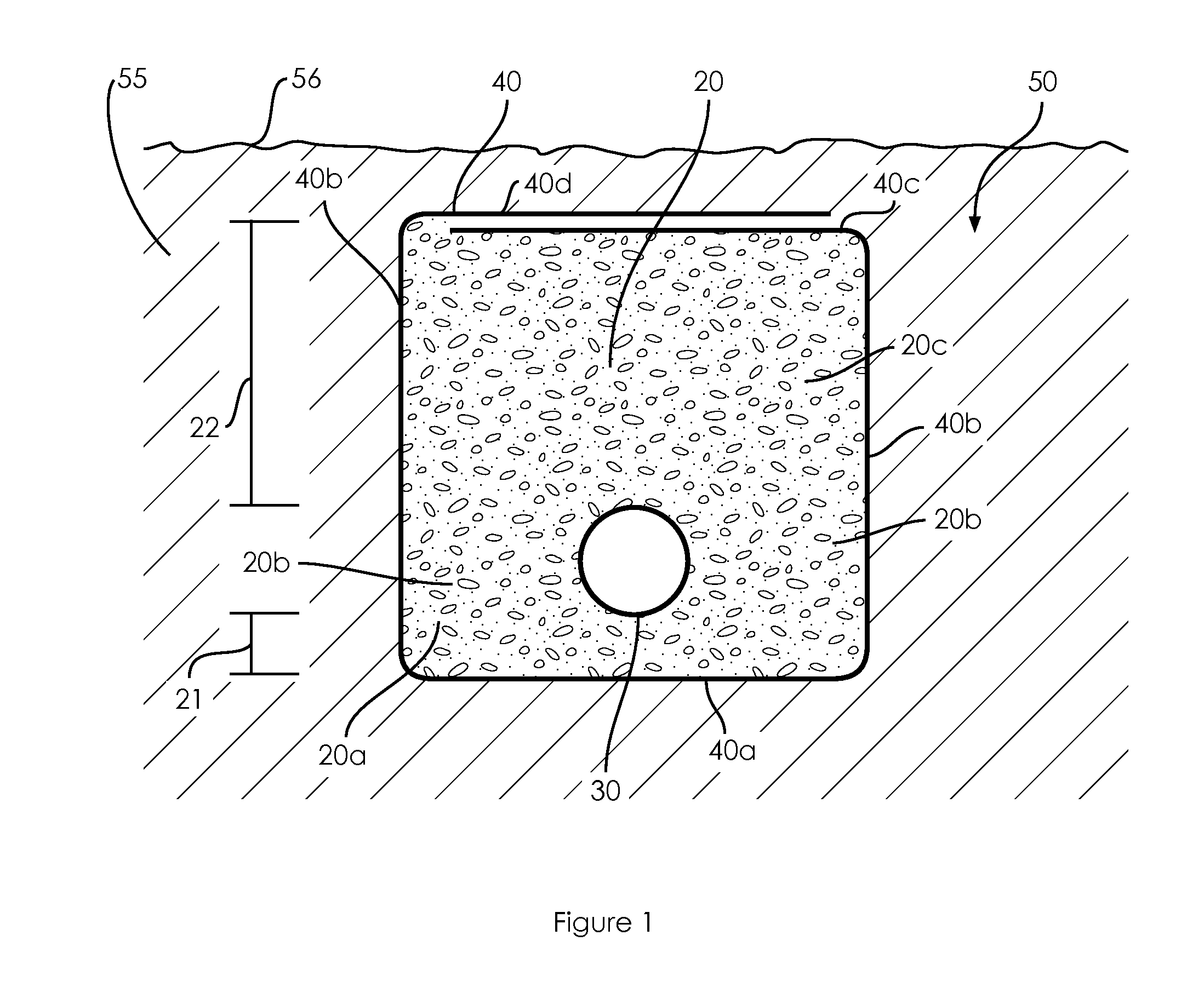
  • Apparatus, an assembly, a vehicle and a method for forming a drainage assembly within and along an elongate trench
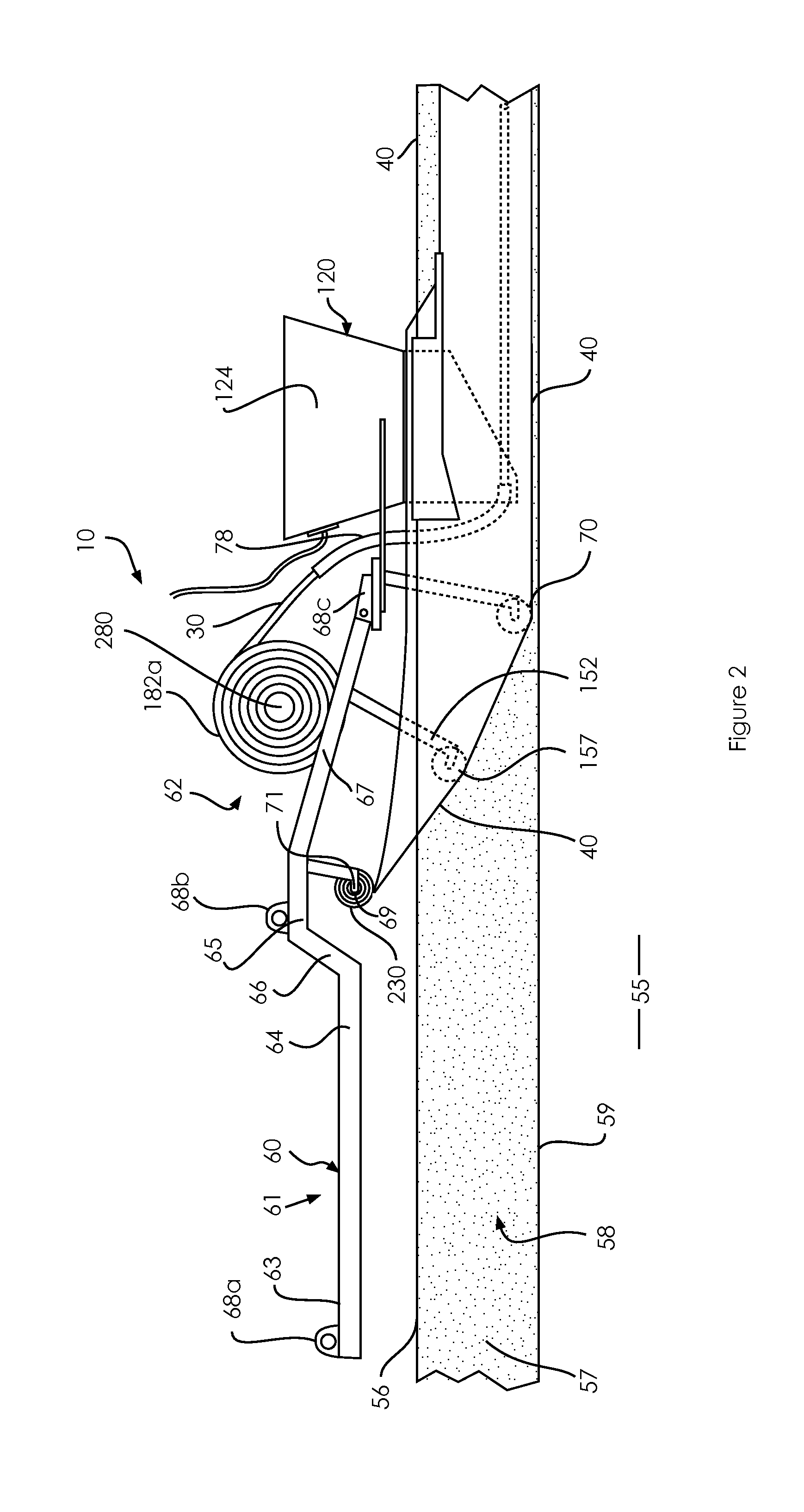
  • Apparatus, an assembly, a vehicle and a method for forming a drainage assembly within and along an elongate trench

Examples


Embodiment Construction

[0282]As required, detailed embodiments of the present invention are disclosed herein; however, it is to be understood that the disclosed embodiments are merely exemplary of the invention, which can be embodied in various forms. Therefore, specific structural and functional details disclosed herein are not to be interpreted as limiting, but merely as a basis for the claims and as a representative basis for teaching one skilled in the art to variously employ the present invention in virtually any appropriately detailed structure. Further, the terms and phrases used herein are not intended to be limiting; but rather, to provide an understandable description of the invention. While the specification concludes with claims defining the features of the invention that are regarded as novel, it is believed that the invention will be better understood from a consideration of the following description in conjunction with the drawing figures, in which like reference numerals are carried forwar...


PUM


Abstract

An apparatus for forming a drainage assembly within and along an elongate trench is disclosed. The apparatus includes a conduit guide means adapted to dispose a length portion of the elongate conduit within the trench, and an aggregate material delivery means adapted to distribute aggregate material within the trench such that the length portion of the elongate conduit within the trench is substantially surrounded by the aggregate material. Movement of the apparatus along the trench in use disposes subsequent length portions of the elongate conduit and further aggregate material within and along the trench to form the drainage assembly.

Description

CROSS-REFERENCE TO RELATED APPLICATIONS[0001]This application is a continuing application, under 35 U.S.C. §120, of co-pending international application No. PCT / AU2011 / 001668, filed Dec. 23, 2011, which designated the United States and was published in English; this application also claims the priority, under 35 U.S.C. §119, of Australian patent application Nos. 2010905622 filed Dec. 23, 2010, and 2011903676 filed on Sep. 8, 2011; the prior applications are herewith incorporated by reference in their entirety.STATEMENT REGARDING FEDERALLY SPONSORED RESEARCH OR DEVELOPMENT[0002]Not ApplicableFIELD OF THE INVENTION[0003]The present invention relates to an apparatus, an assembly, a vehicle and a method for continuously forming a drainage assembly along an elongate trench.[0004]The invention has been developed primarily for use in construction of roads and railways, drainage, landscaping, agriculture and building construction industries and will be described hereinafter with reference t...

Claims


Application Information

Patent Timeline
Patent Type & Authority Applications(United States)
IPC IPC(8): E02B11/02
CPCE02B11/02E02B11/005
Inventor WILSON, MARK
Owner DITJET INTPROP PTY
Learn More