Window regulator assembly for a vehicle

a technology for window regulators and vehicles, applied in door frames, wing accessories, transportation and packaging, etc., can solve the problems of the configuration of the lifter plate assemblies themselves, the force required to insert a window into the lifter plate assembly is relatively high, and the joint between the pulleys and the carrier may be subject to premature failur

Active Publication Date: 2014-02-13
MAGNA CLOSURES INC
View PDF12 Cites 9 Cited by
  • Summary
  • Abstract
  • Description
  • Claims
  • Application Information

AI Technical Summary

Benefits of technology

The patent describes a window lifter plate for vehicles that has various features to securely hold and protect the window. The lifter plate includes a first and second side walls with a window pass-through member in between. The window pass-through member has a connected end and a free end, with the connected end connected to the first side wall. The second side wall includes a free end vertical limit surface that is positioned to engage the free end to limit upward movement of the free end. The window pass-through member is prevented from rotating away from the vertical limit surface when a force is applied to remove the lifter plate. The lifter plate also has lateral engagement surfaces that are biased against lateral guide surfaces to accommodate lateral forces with a reduced tendency to bind. The window regulator system includes a drive motor, lifter plates, drive cables, and a down stop that prevents further travel of the drive cable when the lifter plates reach a selected position. The lifter plate also has window locking features that engage the undercuts of the window when the window is inserted into the lifter plate.

Problems solved by technology

There are several problems, however, with these window regulator assemblies.
Due to the forces involved in moving the window, however, the joint between the pulleys and the carrier may be subject to premature failure.
Another problem resides in the configuration of the lifter plate assemblies themselves.
However, the force required to insert a window into the lifter plate assembly is relatively high.
Another problem is that the window regulator lifter plate assemblies are prone to binding or sticking as they move along the rails.
However, the large motors increase the overall cost of the window regulator assemblies.
Another problem is that, when a door handle assembly is mounted to the carrier, the door handle itself can swing during transport or during installation of the carrier in a door assembly, which can cause the door handle to catch on something, potentially causing damage.

Method used


Image

  • Window regulator assembly for a vehicle
  • Window regulator assembly for a vehicle
  • Window regulator assembly for a vehicle

Examples


Embodiment Construction

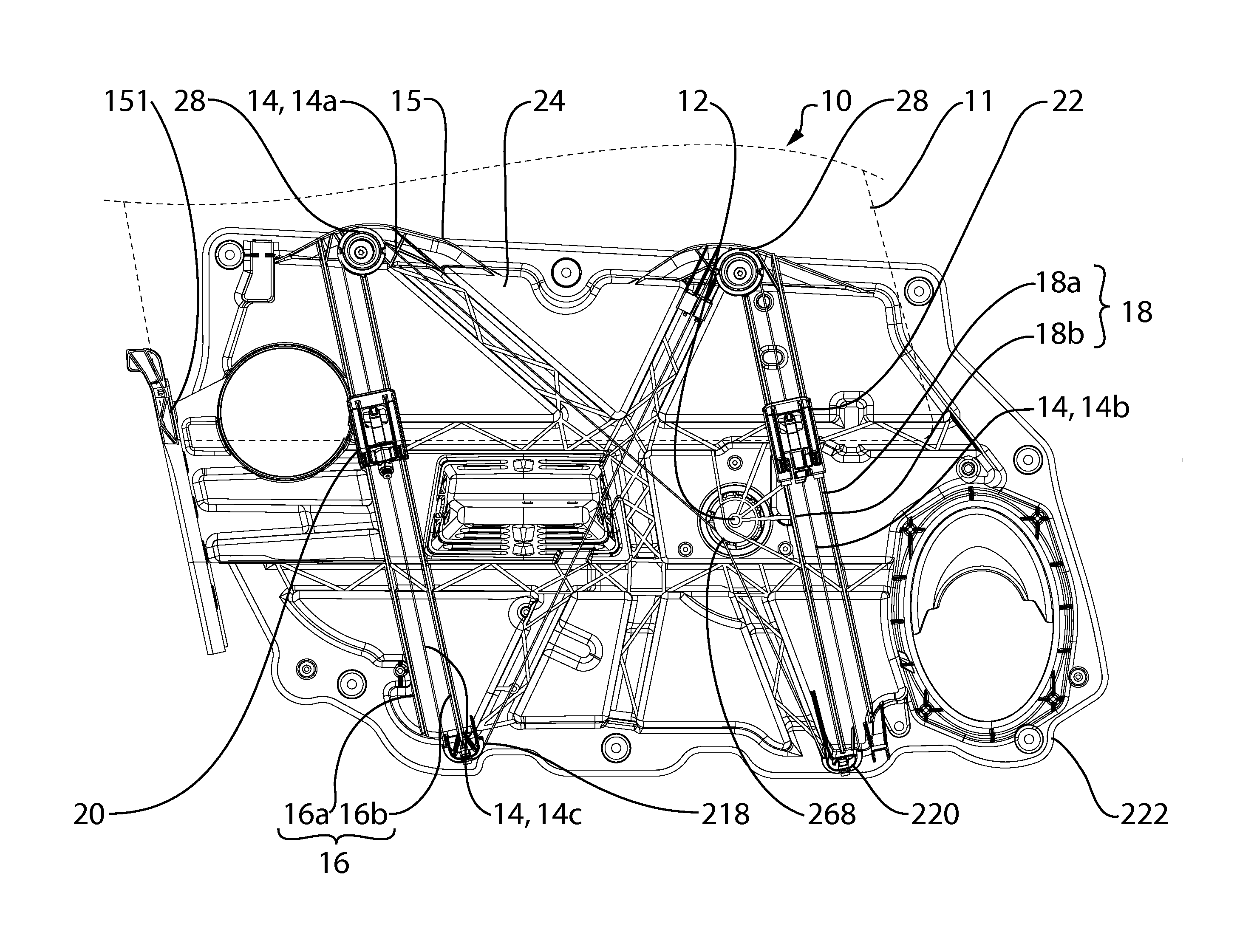
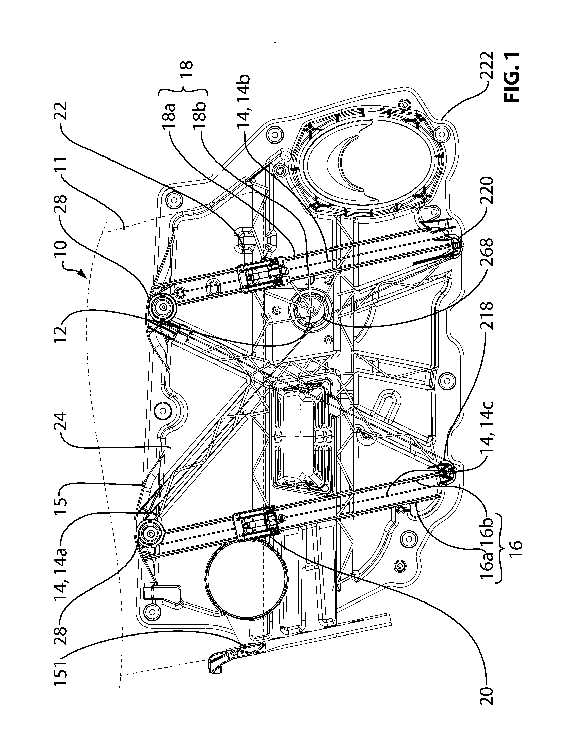
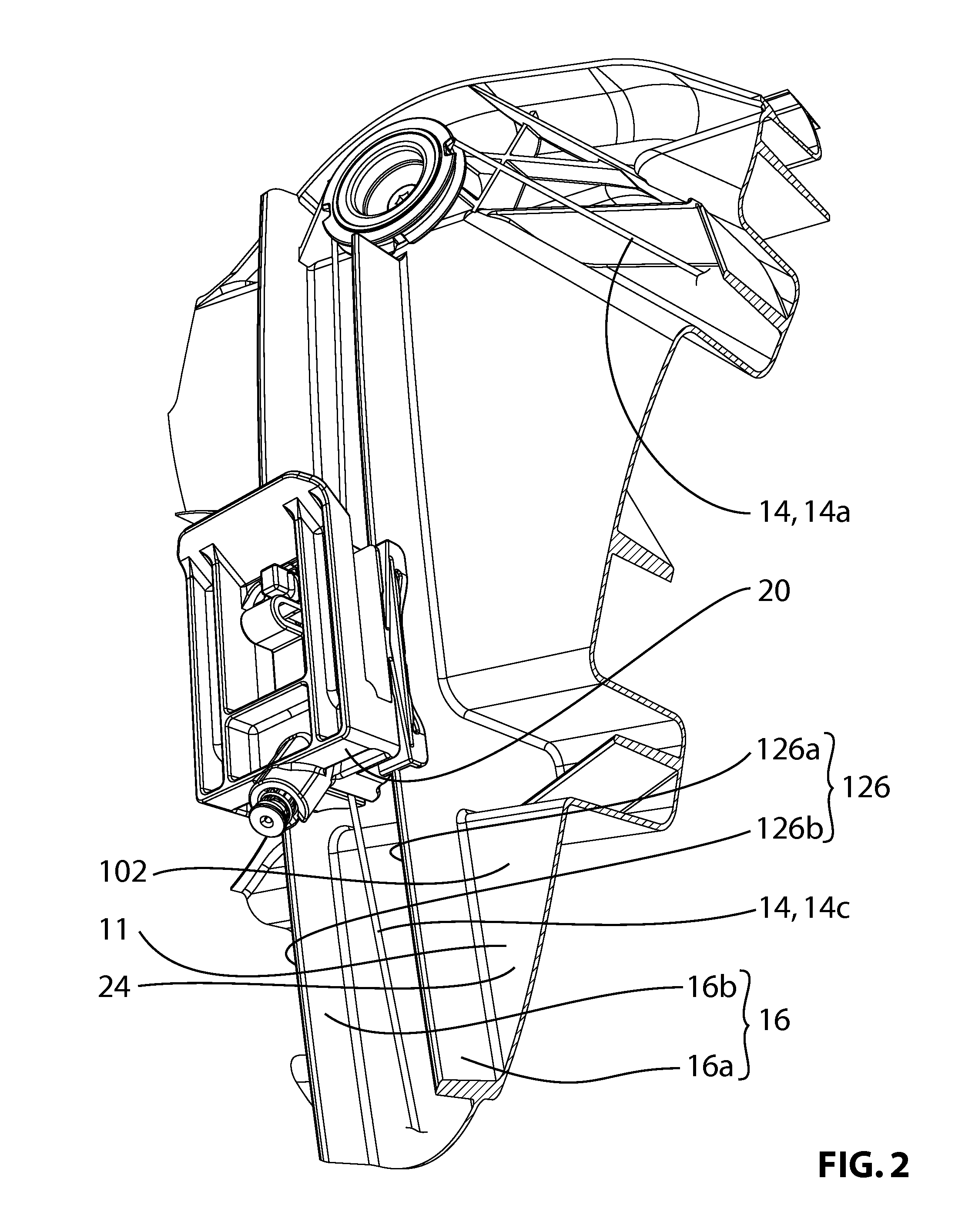
[0077]Reference is made to FIG. 1, which shows a window regulator assembly 10 for moving a vehicle window 11 up and down in accordance with an embodiment of the present invention. The window regulator assembly 10 includes a drive motor 12, a set of drive cables 14, including a first drive cable 14a, a second drive cable 14b and a third drive cable 14c, a carrier 15, which includes a first set of rails 16 and second set of rails 18, a first lifter plate 20 and a second lifter plate 22.

[0078]The drive motor 12 drives vertical movement of the first and second lifter plates 20 and 22 on the set of rails 16 and 18 respectively by means of the drive cables 14.

[0079]The carrier 15 is itself mountable to the interior of a door assembly (not shown) that forms part of a vehicle. In the embodiment shown in FIG. 1, the carrier 15 is a structural element, and is configured to withstand loads incurred during operation of window regulator assembly 10. The carrier 15 includes a carrier body 24 and ...


PUM


Abstract

In an aspect, a lifter plate is provided that is capable of a relatively strong connection to a vehicle window. The lifter plate includes a lifter plate body including a first side wall and a second side wall configured to receive a vehicle window therebetween, a window holding member positionable in a locking position to prevent the withdrawal of the vehicle window from between the first and second side walls, and a locking member positioned to prevent the movement of the window holding member out of the locking position in the event of a force urging the withdrawal of the vehicle window from between first and second side walls.

Description

CROSS REFERENCE TO RELATED APPLICATIONS[0001]This application is a divisional application of U.S. patent application Ser. No. 12 / 599,162 filed Nov. 6, 2009, which is national phase entry application of PCT / CA2008 / 000892, filed May 9, 2008, which claims the benefit of: U.S. Provisional Application No. 60 / 916,860, filed May 9, 2007 and U.S. Provisional Application No. 60 / 968,364, filed Aug. 28, 2007.FIELD OF THE INVENTION[0002]The present invention relates to window regulator assemblies for vehicles.BACKGROUND OF THE INVENTION[0003]Vehicle doors typically have windows that can be opened and closed. Within the door, there is typically a window regulator assembly including a carrier, a motor, first and second rails and two window regulator lifter plate assemblies which are driven along the rails by the motor.[0004]There are several problems, however, with these window regulator assemblies. For example, in situations where the window regulator lifter plate assemblies are driven by cables...

Claims


Application Information

Patent Timeline
Patent Type & Authority Applications(United States)
IPC IPC(8): B60J1/17E05F15/08
CPCE05F15/086B60J1/17E05F15/689F16H55/50E05Y2900/55E05Y2600/13E05Y2201/668E05Y2201/654B60J5/0416E05F11/382E05F11/385E05F11/483E05F11/485E05F2011/387E05Y2201/224E05Y2201/47E05Y2201/612E05Y2201/684E05Y2800/29E05Y2800/692E05Y2600/00E05Y2800/26E05Y2600/53E05Y2900/50E05Y2201/706B60J1/007B60J5/0402B60J5/0408B60J5/06E05F11/488
Inventor BROADHEAD, DOUGLAS G.FORTIN, RAYMOND EDWARDMIU, TRAIANMELLARY, THOMASFERRI, JAMES J.SMITH, DONALD HARRY
Owner MAGNA CLOSURES INC
Why Eureka
Try Eureka