Check patentability & draft patents in minutes with Patsnap Eureka AI!

Removable payload containment systems for platforms, installation methods thereof, and payload integration kits for existing platforms

Active Publication Date: 2014-02-13
US SEC THE ARMY THE
View PDF7 Cites 21 Cited by
  • Summary
  • Abstract
  • Description
  • Claims
  • Application Information

AI Technical Summary

Benefits of technology

The patent text describes a system for removably containing payloads on a platform. The system includes a housing with connectors for attaching to the platform, and a latch mechanism that securely attaches to the platform and allows for easy removal. The latch mechanism limits movement of the housing to one direction when the connectors are connected or disconnected. This system can be used as a standalone payload containment system or in conjunction with other components to modify the platform for additional payload functions. The technical effects include the ability for secure and easy removable payload containment on a platform with reduced risk of damage or loss during transport.

Problems solved by technology

Configuring the robot for a particular mission can be quite a lengthy process—not to mention a challenge to mount various and different hardware components and related electronics to the robotic platform.
Fastening and removing the payload container to the robot requires significant time to install or remove the screw fasteners, and the payload container is not water-proof, dust-proof, or shielded to adequately protect sensitive electronic components therein.
Furthermore, and also of particular concern, is that when a connector is being connected to and disconnected from a corresponding connector of the robot and even during use, the fragile connectors are susceptible to damage.
For instance, even slight rotation or pivoting of the payload container with respect to the robot's chassis (or movement in a direction other than required to couple / uncouple the connectors) can shear, break, crush, bend, and / or otherwise damage the pin connections or contacts of the connector, crack or break the wall of connector and / or the payload container, or unintentionally disconnect the connector, among other problems.
In light of these issues, this payload container has proved quite limited for in-field use, and impractical for many applications.

Method used


Image

  • Removable payload containment systems for platforms, installation methods thereof, and payload integration kits for existing platforms
  • Removable payload containment systems for platforms, installation methods thereof, and payload integration kits for existing platforms
  • Removable payload containment systems for platforms, installation methods thereof, and payload integration kits for existing platforms

Examples


Embodiment Construction

[0024]Embodiments of present invention are directed to removable payload containment systems for a platform, installation methods thereof, and payload integration kits for existing platforms. The payload containment systems provide a quick and simple way to add or change capabilities or functionality of a platform with relative ease, and which can be locked into place with a latch mechanism. Accordingly, the platform can be adapted, as needed, for any variety of applications, missions, functions or tasks, by adding the removable payload containment system to, or exchanging the removable payload containment system with the platform.

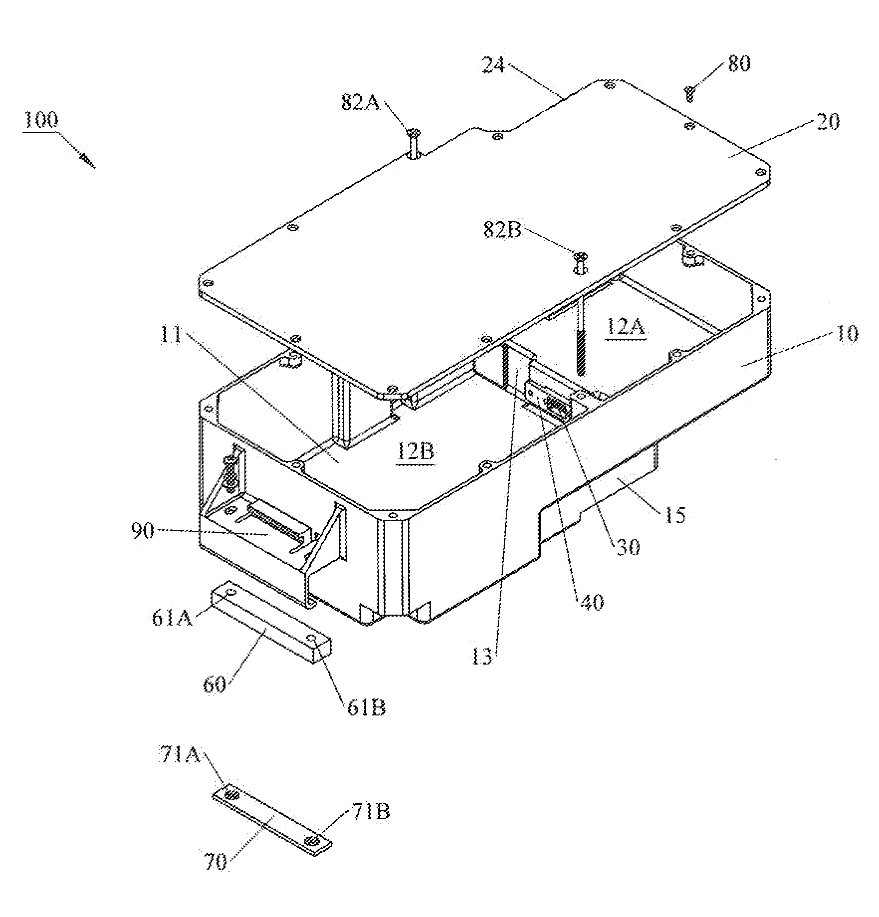
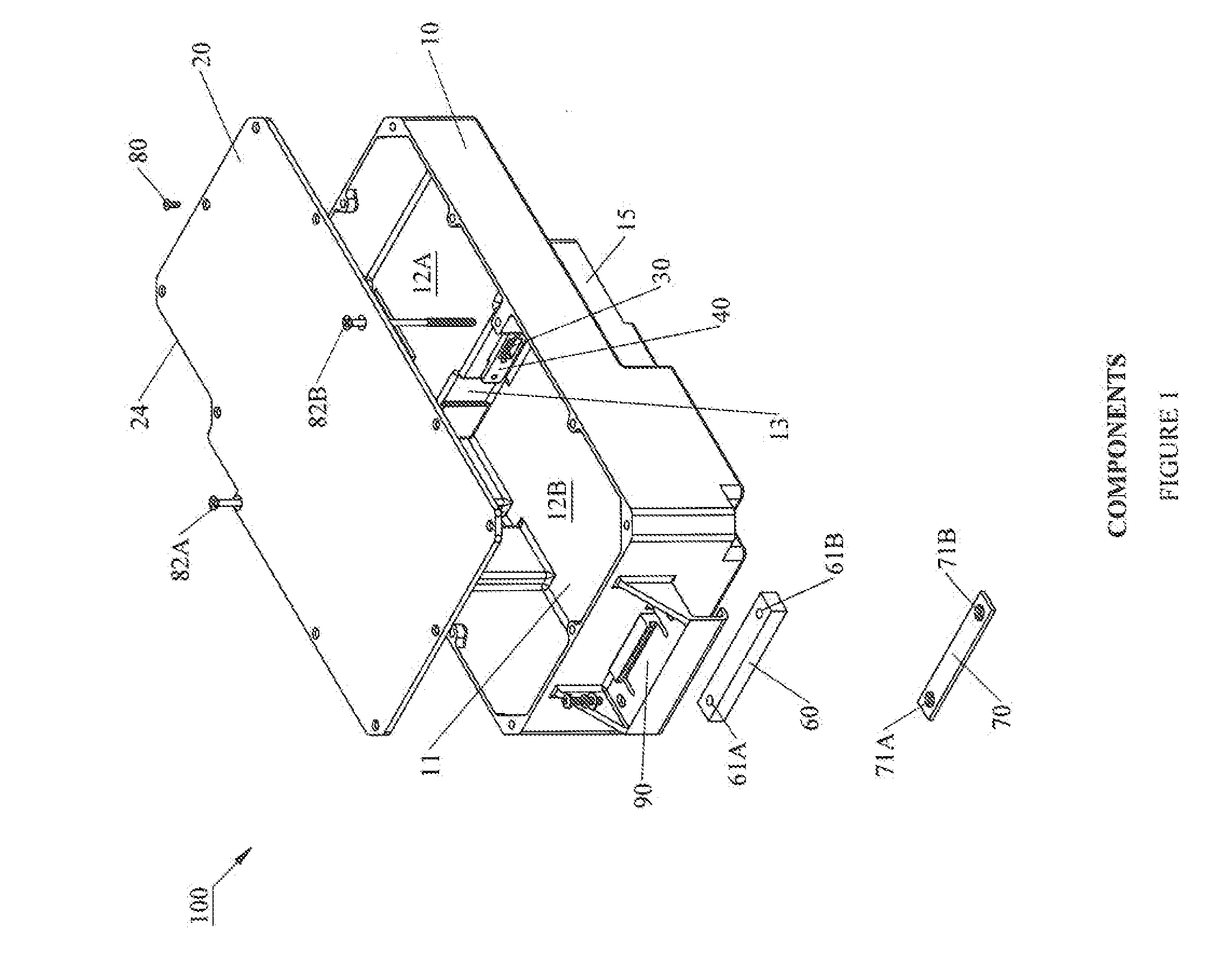
[0025]FIG. 1 illustrates a payload containment system 100 according to an embodiment. As shown, the payload containment system 100 generally includes a housing 10, lid 20, connector 30, connector bracket 40, gaskets 50, spacer 60, nut bar 70, fasteners 80, and a latch mechanism 90. In some embodiments, fewer or additional elements may be provided than are ...


PUM

PropertyMeasurementUnit
Pressureaaaaaaaaaa
Interferenceaaaaaaaaaa
Lengthaaaaaaaaaa

Abstract

Embodiments of the invention are directed to removable payload containment systems for platforms, installation methods thereof and payload integration kits for platforms. The removable payload containment system may include: a housing having internal space for components, the housing including at least one connector configured to couple with at least one corresponding connector of the platform when the system is installed in or on the platform; and a latch mechanism that couples to a member of the platform and is configured to maintain the system into substantially non-moving engagement with the platform when engaged therewith, and permit removal of the system from the platform when released. The latch mechanism may be configured to limit movement of the housing with respect to platform in substantially only one direction when one connector couples and uncouples, and is mated, with a corresponding connector of the platform when installing or removing the system from the platform.

Description

CROSS REFERENCE TO RELATED APPLICATION(S)[0001]The present application claims the benefit of U.S. Provisional Patent Application No. 61 / 680,522 filed Aug. 7, 2012, herein incorporated by reference in its entirety herein.GOVERNMENT INTEREST[0002]The invention described herein may be manufactured, used and licensed by or for the U.S. Government without the payment of royalties thereon.BACKGROUND OF THE INVENTION[0003]1. Field[0004]Embodiments of the present invention generally relate to payload containment systems, and in particular, to removable payload containment systems for various platforms.[0005]2. Description of Related Art[0006]The U.S. Army is developing various intelligent, autonomous robotic systems. Example robots include, for instance, Small Unmanned Ground Vehicle (SUGV) Model Nos. 310 and 320 available from iRobot Corporation of Somerville, Mass. The robots may be configured for various missions, which may require markedly different hardware and component configurations...

Claims


Application Information

Patent Timeline
IPC IPC(8): B60R7/02
CPCB60R7/02Y10T29/49826Y10T29/53
Inventor GREGORY, JR., RICHARD R.
Owner US SEC THE ARMY THE
Features
  • R&D
  • Intellectual Property
  • Life Sciences
  • Materials
  • Tech Scout
  • Unparalleled Data Quality
  • Higher Quality Content
  • 60% Fewer Hallucinations
Learn More