

Rotor and manufacturing process of rotor
- Summary
- Abstract
- Description
- Claims
- Application Information
AI Technical Summary
Benefits of technology
Problems solved by technology
Method used
Image

Examples
first preferred embodiment
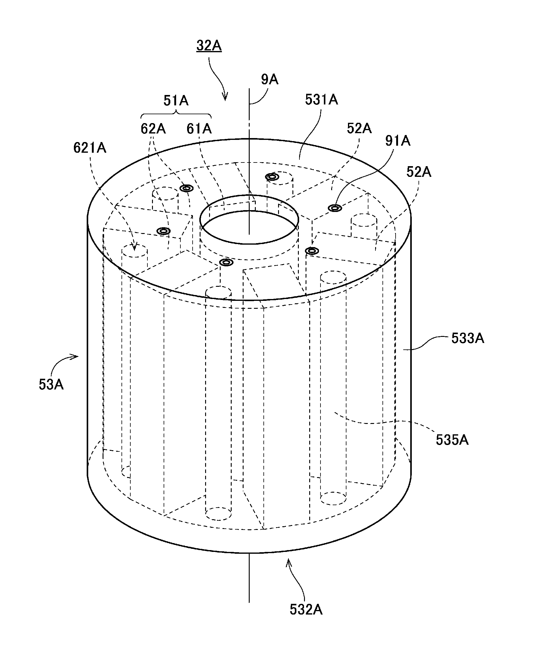
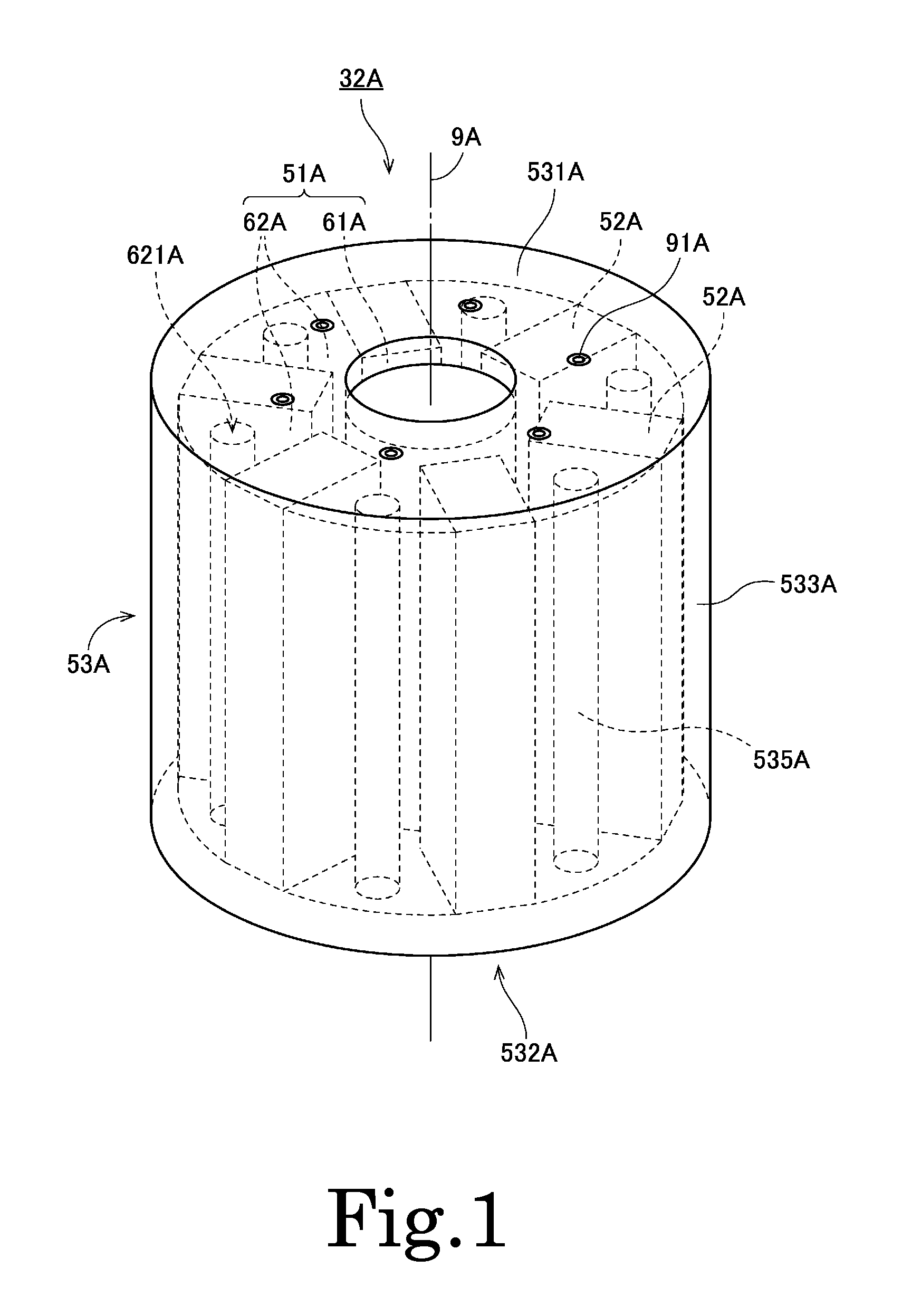
[0028]FIG. 1 is a perspective view of a rotor 32A according to a first preferred embodiment of the present invention. The rotor 32A is preferably for use in an inner rotor type motor. As illustrated in FIG. 1, the rotor 32A preferably includes a laminated core 51A, a plurality of magnets 52A, and a resin portion 53A. The laminated core 51A is preferably defined by a plurality of thin plate cores laminated in the axial direction. The plurality of magnets 52A are arranged in the circumferential direction around a center axis 9A extending vertically. The resin portion 53A is preferably obtained by, for example, injection molding.
[0029]The laminated core 51A preferably includes an inner core portion 61A and a plurality of outer core portions 62A. The inner core portion 61A axially extends in a cylindrical shape in a region located farther radially inward than the magnets 52A. The plurality of outer core portions 62A are arranged in the circumferential direction in a region located farth...
second preferred embodiment
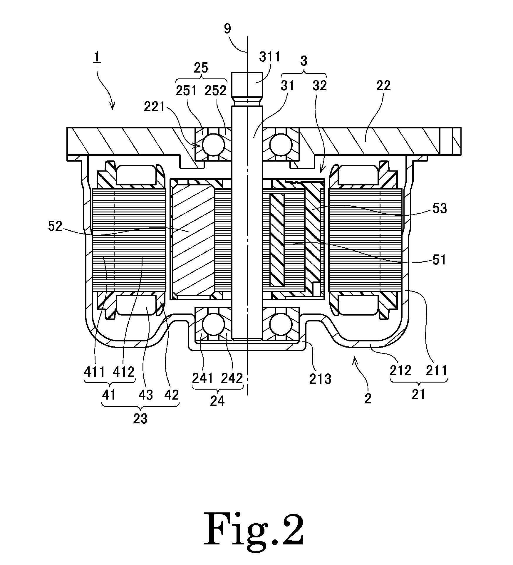
[0035]Subsequently, a second preferred embodiment of the present invention will be described. FIG. 2 is a longitudinal sectional view of a motor 1 according to the second preferred embodiment. The motor 1 in this preferred embodiment is preferably mounted in, for example, a vehicle and is used to generate a driving force for power steering. However, the motor according to various preferred embodiments of the present invention may also be used for any desirable purpose other than power steering. For example, the motor according to various preferred embodiments of the present invention may also be used as a driving source of another part of a vehicle such as an engine cooling fan, an oil pump, etc. In addition, the motor according to various preferred embodiments of the present invention may be mounted in electric appliances, office automation equipment, medical equipment, etc. to generate various driving forces, for example.
[0036]The motor 1 is a so-called inner rotor type motor in w...
PUM
 Abstract
Description
Claims
Application Information