Waste toner collector and image forming apparatus

a technology of image forming apparatus and waste toner, which is applied in the field of waste toner collector and image forming apparatus, can solve the problems of insufficient containment, difficult to increase the size of the waste toner collection container as a whole, and accumulated waste toner at a portion of the waste toner collection container, so as to improve the efficiency of waste toner containing and large volume

Active Publication Date: 2014-02-13
KONICA MINOLTA INC
View PDF7 Cites 54 Cited by
  • Summary
  • Abstract
  • Description
  • Claims
  • Application Information

AI Technical Summary

Benefits of technology

[0008]The present invention is made in view of the situation described above, and a technical object thereof is to improve waste toner containing efficiency of a waste toner collector having a complicated shape with recesses and protrusions to secure a large volume.

Problems solved by technology

However, due to the recent demand for downsizing of image forming apparatuses, a space to dispose the waste toner collecting container is limited, and thus it is difficult to increase the size of the waste toner collecting container as a whole.
However, if the waste toner collecting container has a complicated outer shape with recesses and protrusions as in the conventional practice, it is difficult to distribute the waste toner over a wide area inside the waste toner collecting container.
Thus, even when a large volume of the waste toner collecting container is secured, the waste toner is accumulated at a portion in the waste toner collecting container and cannot be sufficiently contained.

Method used


Image

  • Waste toner collector and image forming apparatus
  • Waste toner collector and image forming apparatus
  • Waste toner collector and image forming apparatus

Examples


first embodiment

2. First Embodiment of Waste Toner Collector

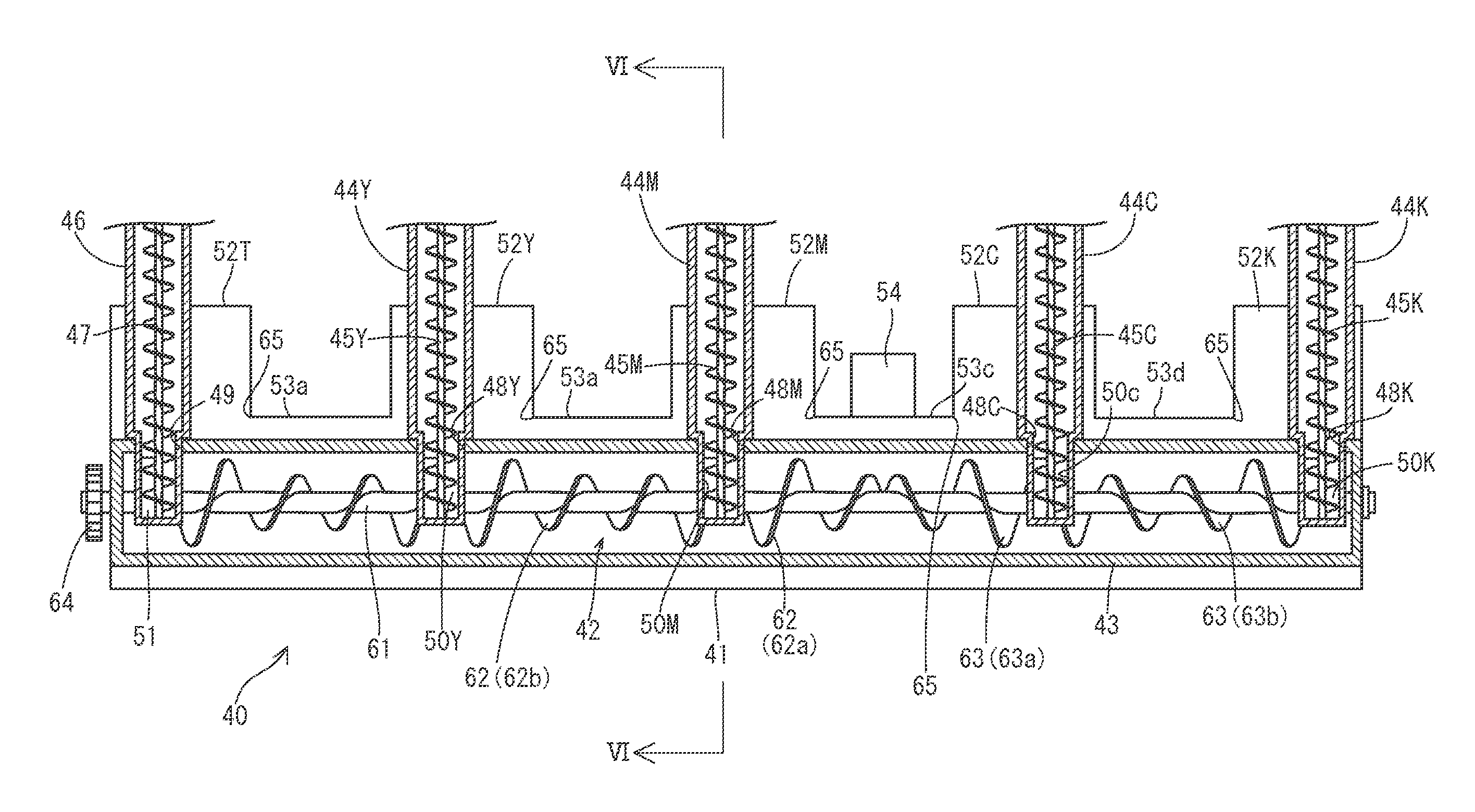
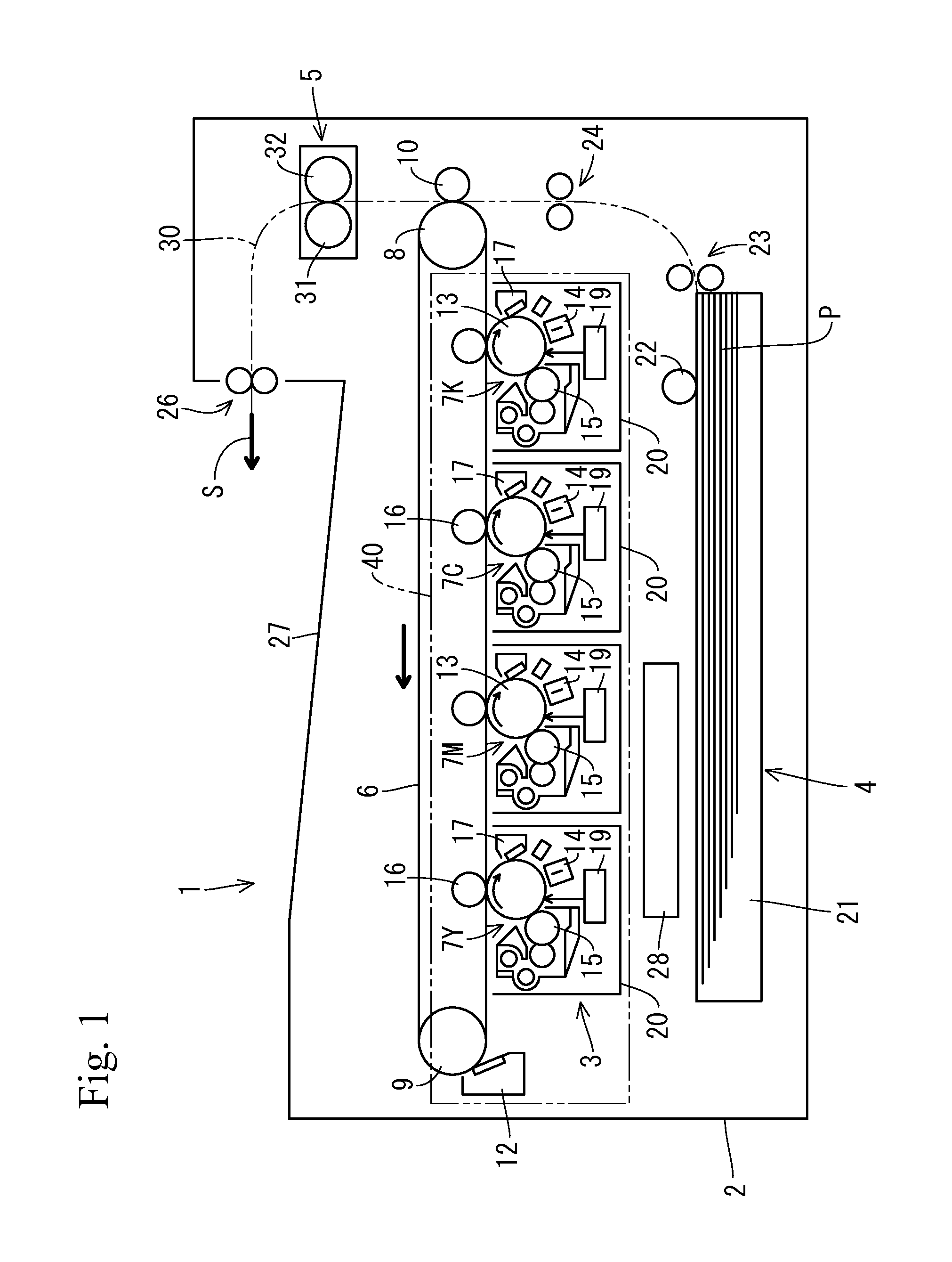
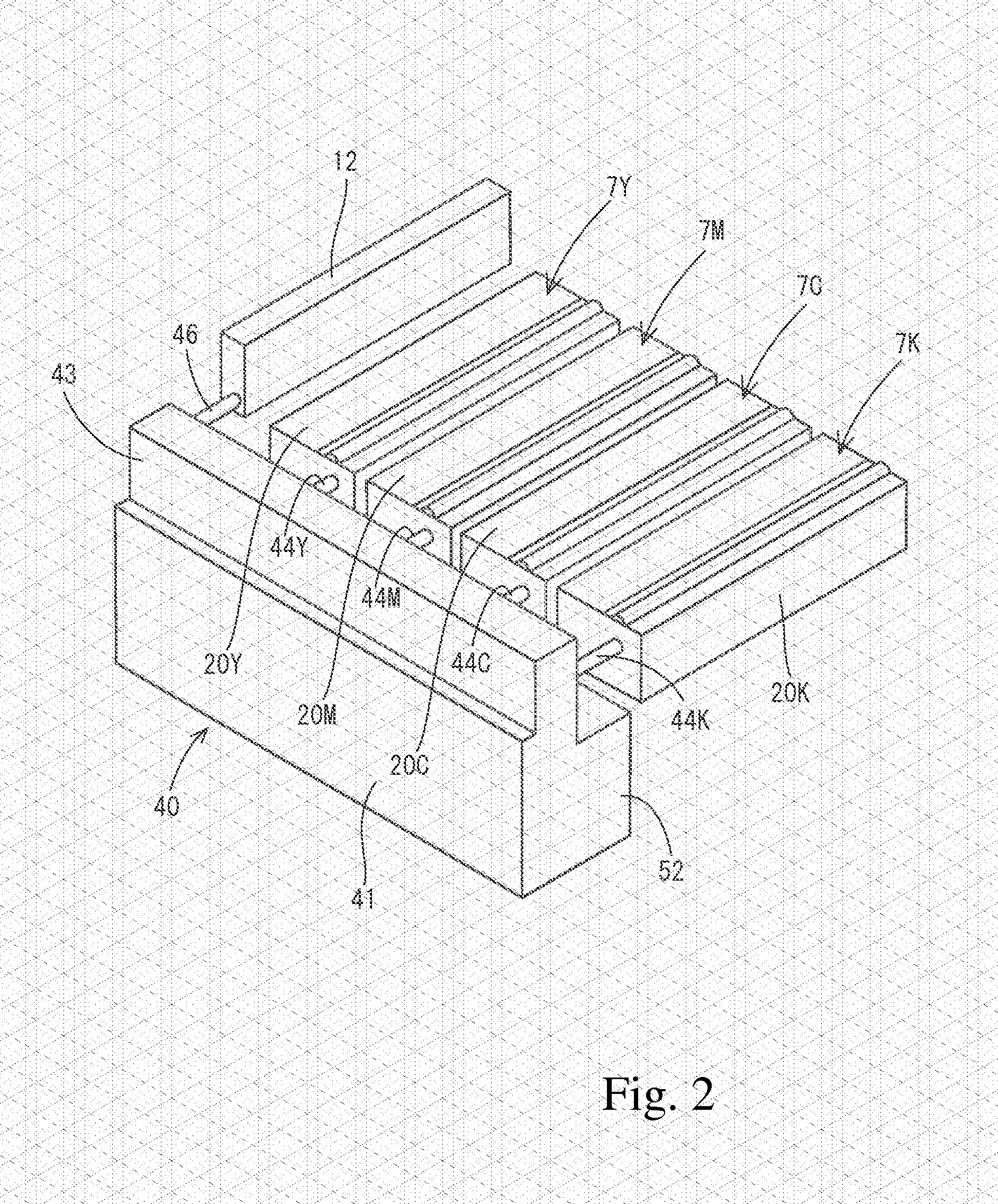
[0038]Next, a first embodiment of the waste toner collector 40 will be described with reference to FIG. 2 to FIG. 6. The waste toner collector 40 on the front side of the image processor 3 in the casing 2 includes a container main body 41 and a dispersion screw 42. The container main body 41 stores therein waste toner (un-transferred toner) removed from the photoreceptor drums 13 and the intermediate transfer belt 6. The dispersion screw 42 serves as a conveyance member that coveys the waste toner in the container main body 41. The container main body 41 has a hollow, laterally long box shape extending over the four image forming units 7 (housings 20) and the transfer belt cleaner 12. The container main body 41 is provided with, on an upper wall side, a waste toner introduction unit 43 protruding upward and extending substantially entirely over the container main body 41 in the longitudinal direction (left-right direction). The waste toner...

second embodiment

3. Second Embodiment of Waste Toner Collector

[0052]FIG. 7 shows a second embodiment of the waste toner collector 40. Here, in this alternative embodiment of the waste toner collector 40 described below, components of which the configuration and the operation are the same as the counterparts of the first embodiment are denoted with the same reference numerals and will not be described in detail. The waste toner collector 40 of the second embodiment shown in FIG. 7 has the same configuration as that of the first embodiment except for the following point. Specifically, the screw blades 62 and 63 of dispersion screw 42 each have the uniform outer diameter D over the entire length, but in the screw blades 62 and 63, a pitch Ps in the portions 62b and 63b corresponding to the recesses 53 is smaller than a pitch Pl in the portions 62a and 63a corresponding to the protruding containing portions 52.

[0053]As described above, in the screw blades 62 and 63, the pitch Ps in the portions 62b and ...

third embodiment

4. Third Embodiment of Waste Toner Collector

[0054]FIG. 8 shows a third embodiment of the waste toner collector 40. The waste toner collector 40 of the third embodiment shown in FIG. 8 has the same configuration as that of the first embodiment except for the following point. Specifically, the rotary shaft 61 has the screw blades 62 and 63 at portions corresponding to the protruding containing portions 52, and paddle blades 70 at portions corresponding to the recesses 53.

[0055]The paddle blade 70 is involved in the stirring of the waste toner piled up around the recess 53 of the container main body 41, but is not involved in the conveyance of the waste toner from the both ends to the intermediate portion of the container main body 41 in the longitudinal direction. Thus, in the dispersion screw 42, the waste toner conveyance force Fs of the paddle blades 70 corresponding to the recesses 53 is almost zero, and thus is smaller than the waste toner conveyance force Fl of the screw blades ...


PUM


Abstract

A waste toner collector of the present invention includes: a container main body configured to collect and store waste toner; and a conveyance member configured to convey the waste toner in the container main body. The container main body is provided with, on one side wall, a plurality of protruding containing portions that protrude outward from the container main body and are disposed along a longitudinal direction of the container main body, and a plurality of recesses each positioned between adjacent ones of the protruding containing portions. The conveyance member extends along the longitudinal direction of the container main body and is rotatably disposed in the container main body. Waste toner conveyance force of the conveyance member in a rotary shaft direction varies in such a manner that, at border portions between the protruding containing portions and the recesses, the waste toner is pushed toward the protruding containing portions.

Description

CROSS-REFERENCE TO RELATED APPLICATIONS[0001]This nonprovisional application claims priority under 35 U.S.C. §119(a) on Patent Application No. 2012-178806 filed in Japan on Aug. 10, 2012, the entire contents of which are hereby incorporated by reference.BACKGROUND OF THE INVENTION[0002]1. Field of the Invention[0003]The present invention relates to a waste toner collector and an image forming apparatus using the same. The image forming apparatus includes copiers, printers, fax machines, and multi-function machines integrally incorporating copy, printing, and fax capabilities.[0004]2. Discussion of the Background[0005]Conventionally, in an electrophotographic image forming apparatus, waste toner removed from a photoreceptor drum and an intermediate transfer belt by a cleaning device has been conveyed by a conveyance screw to be collected in a waste toner collecting container (see, for example Japanese Unexamined Patent Application Publication No. 2012-42789 and Japanese Unexamined Pa...

Claims


Application Information

Patent Timeline
Patent Type & Authority Applications(United States)
IPC IPC(8): G03G21/00G03G21/12
CPCG03G21/12G03G21/105
Inventor MEKADA, HIDEKI
Owner KONICA MINOLTA INC
Why Eureka
Try Eureka