Vehicle with a safety system involving prediction of driver tiredness

a safety system and driver technology, applied in the direction of driver input parameters, non-deflectable wheel steering, electric devices, etc., can solve the problems of inability to safely warn drivers by the current methods, inability to detect fatigue, so as to increase traffic safety

Active Publication Date: 2014-02-13
SCANIA CV AB
View PDF19 Cites 13 Cited by
  • Summary
  • Abstract
  • Description
  • Claims
  • Application Information

AI Technical Summary

Benefits of technology

[0038]The method and system according to the invention might also give the driver and / or haulier / control centre a direct estimate, from the start of the driving shift, of when during a journey the driver will be assessed as tired. Humans are good at estimating their own tiredness but not at trusting themselves or appreciating likely consequences.
[0039]No need for driver to input any information. Information is gathered from vehicle.
[0040]No further sensors required to measure driver behaviour.
[0041]Warnings which are uncertain result in low acceptance; the method according to the invention adjusts existing systems to increase traffic safety when accidents are more likely to occur.

Problems solved by technology

It is difficult to prove, but as many as 40% of all vehicle accidents could be due to tiredness.
The risk of generating unfounded warnings which are therefore not accepted means that there is no way to safely warn drivers by the methods currently available.
A difficulty with many of the systems currently used to warn the driver when he / she is tired is in the individual adaptation of systems, since it is not possible to use a general threshold value applicable to all drivers, which makes it inappropriate to warn the driver directly.
The systems therefore only marginally increase traffic safety and there is a risk that acceptance of all similar systems will be low if false warnings commonly occur.
Certain methods require a great deal of extra equipment which the driver must carry or information which the driver must put into the system / method manually.

Method used


Image

  • Vehicle with a safety system involving prediction of driver tiredness
  • Vehicle with a safety system involving prediction of driver tiredness
  • Vehicle with a safety system involving prediction of driver tiredness

Examples


Embodiment Construction

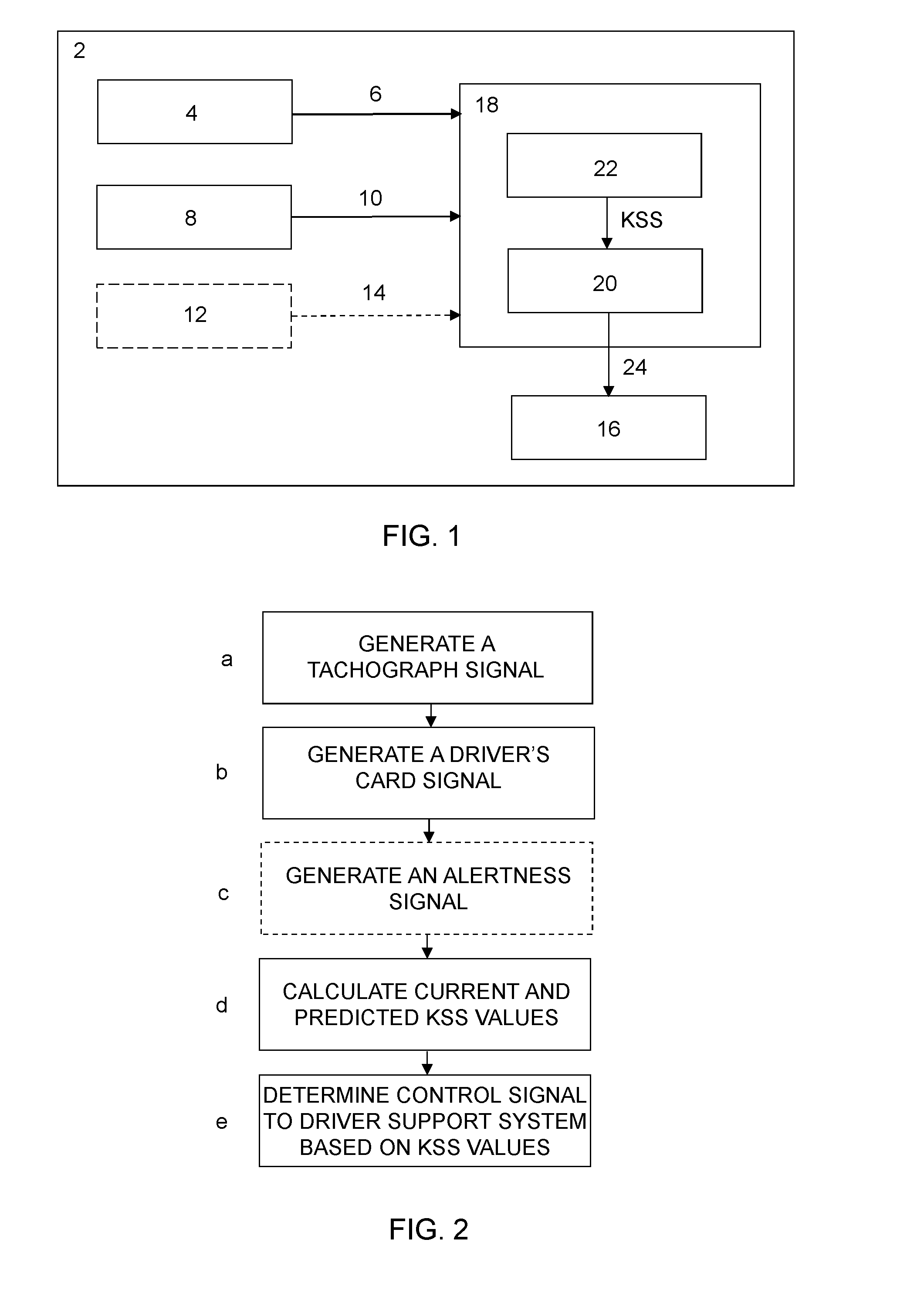
[0050]With reference to the attached figures, the invention will now be described in detail.

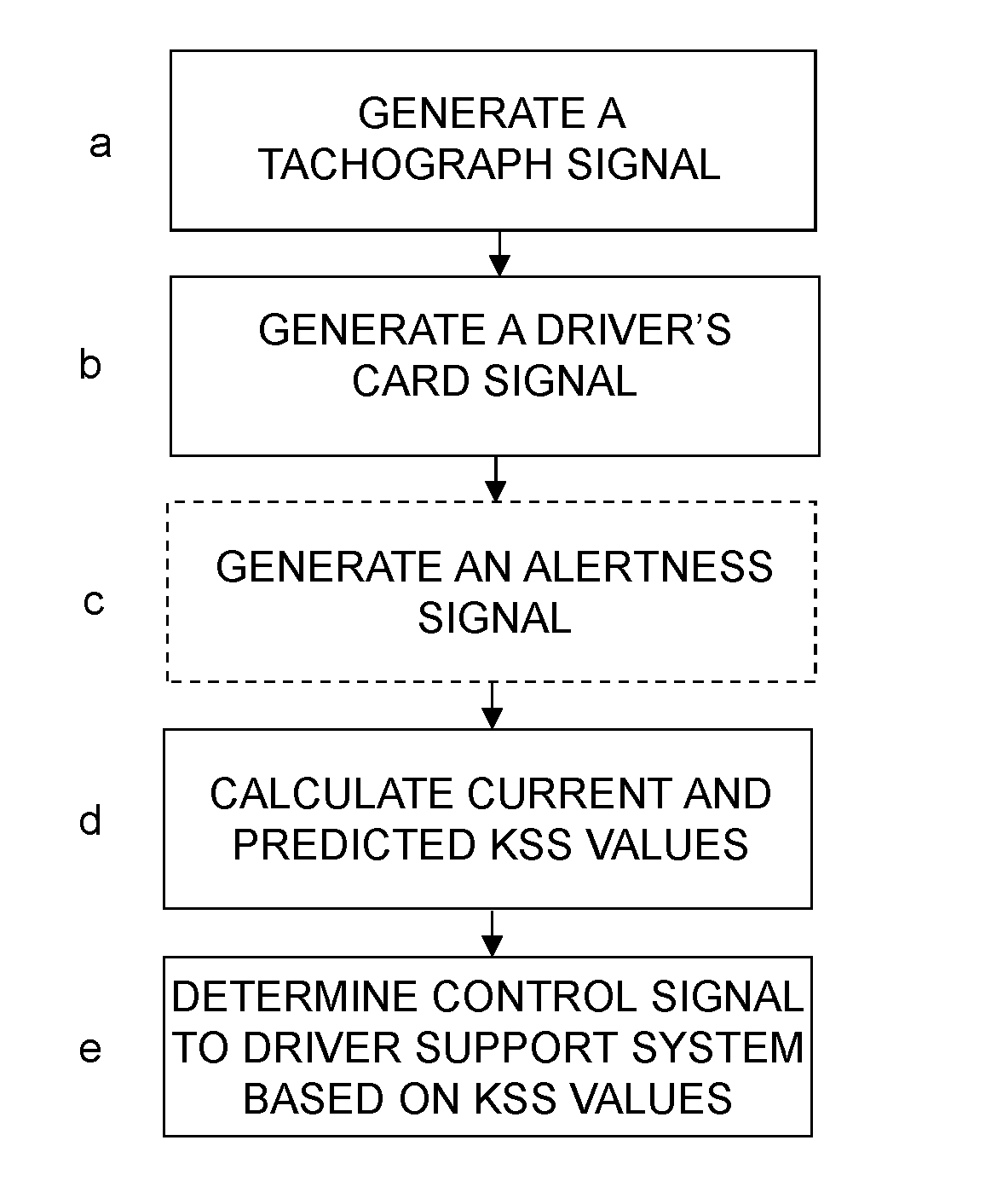
[0051]Firstly with reference to FIG. 1, which shows a schematic block diagram of the invention.

[0052]The invention thus comprises a vehicle 2, e.g. a truck, bus or car, provided with a tachograph 4 adapted to generate a tachograph signal 6 containing inter alia information about current clock time and the times of the vehicle's movements. The vehicle further comprises a driver's card input unit 8 adapted to generate a driver's card signal 10 containing inter alia information about driving and rest times for the driver, and preferably a monitoring system 12 for monitoring of driver activity which is adapted to generate an alertness signal 14 containing information about the driver's activity in the vehicle. The monitoring system may take the form of motion sensors so positioned that they can, for example, detect the driver's movements in the driving seat or his / her eye movements. Other movemen...


PUM


Abstract

A vehicle (2) has a tachograph (4) which generates a tachograph signal (6) containing information about current clock time and the times of the vehicle's movements, a driver's report input unit (8) generates a signal (10) containing information about driving and rest times for the driver, including monitoring (12) of driver activity which generates an alertness signal (14) containing information about the driver's activity in the vehicle. A safety system (18) has a control unit (20) and an alertness modelling unit (22) which calculates a current and a predicted tiredness values (KSS) for the driver based on the tachograph signal (6) and / or the driver's report signal (10). The tiredness values are conveyed to a control unit which determines control signals (24) for the vehicle's driver support systems.

Description

FIELD OF THE INVENTION[0001]The present invention relates to a vehicle with a safety system and a method for such a vehicle, according to the preambles of the independent claims.BACKGROUND TO THE INVENTION[0002]It is difficult to prove, but as many as 40% of all vehicle accidents could be due to tiredness. The risk of generating unfounded warnings which are therefore not accepted means that there is no way to safely warn drivers by the methods currently available.[0003]Within the research community, it is accepted that there is a connection between tiredness and steering behaviour, how well a vehicle stays in its traffic lane and even how human beings blink. There is however no single threshold value or single function such that a certain value / behaviour would consistently indicate that a driver is tired.[0004]U.S. Pat. No. 6,313,749 B1 relates to detection of vehicle driver tiredness, uses a number of different sensors to detect the vehicle's status and the driver's alertness, and ...

Claims


Application Information

Patent Timeline
Patent Type & Authority Applications(United States)
IPC IPC(8): B60R21/00
CPCB60R21/00B60W50/0097B60W2050/146B60W2540/18B60W2540/22G08B21/06G08B31/00B60W2040/0809B60W2040/0818B60W2040/0872G07C5/02G07C5/0808B60W40/09B60W2540/043B60W2540/221B60W2556/10B60W2050/0075B60K28/06B60W40/08B60W50/08G07C5/00B60Y2306/13B60W50/06B60W2540/229B60L3/02G07C5/002
Inventor KOLLEGGER, PETERCLAEZON, FREDRICHFRID, ALEXANDRASTROM, FREDRIK
Owner SCANIA CV AB
Why Eureka
Try Eureka