

Double-rotor flux-switching machine
a technology of flux switching machine and double-rotor, which is applied in the direction of magnetic circuit rotating parts, stator/rotor body manufacturing, and shape/form/construction of magnetic circuits, etc., can solve the problems of low torque density of existing flux switching machine and other permanent magnet machines
Active Publication Date: 2014-02-20
RENESSELAER POLYTECHNIC INST
View PDF18 Cites 39 Cited by
- Summary
- Abstract
- Description
- Claims
- Application Information
AI Technical Summary
Benefits of technology
This patent describes novel machines called flux-switching machines (FSMs) that can be used as motors or generators. The FSMs have a unique topology and structure, including a stator with multiple permanent magnets and a coil. The stator is encapsulated in a non-magnetic material and includes a ring-shaped opening. The FSMs also have a variety of different configurations with different numbers and types of coils. The technical effects of this patent are the provision of improved FSMs with improved performance and efficiency, as well as methods for manufacturing and using them.
Problems solved by technology
Existing flux-switching machines show some disadvantages, including relatively low torque density compared to other permanent magnet machines.
Method used
View moreImage
Smart ImageViewing Examples

Examples
embodiment 1
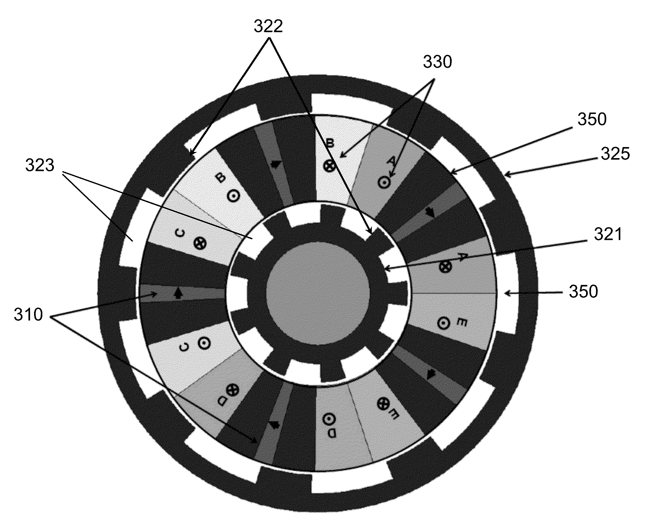
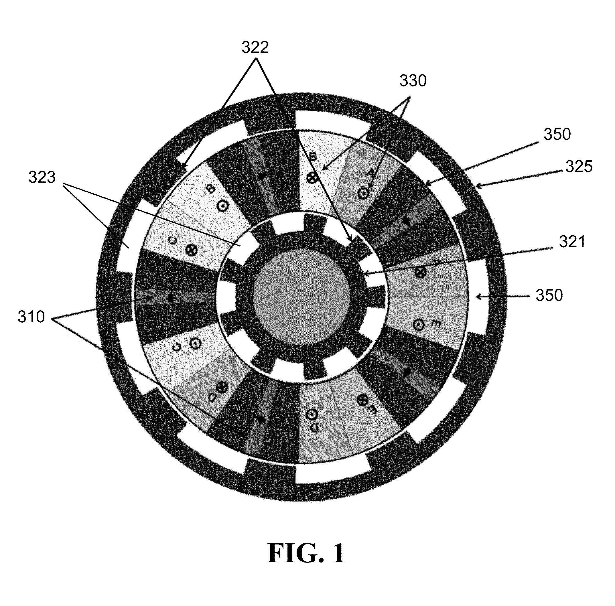
[0104]A flux-switching machine (FSM), comprising:[0105]a first rotor;[0106]a second rotor; and[0107]a stator disposed between the first rotor and the second rotor,[0108]wherein the stator has a ring shape with an annular opening.
embodiment 2
[0109]The FSM according to embodiment 1, wherein the stator comprises at least two permanent magnets and a coil wrapped around each permanent magnet (the coil does not have to be wrapped around the magnet such that the coil is in contact with the magnet; a portion of the stator may be disposed therebetween).
embodiment 3
[0110]The FSM according to embodiment 2, wherein all permanent magnets of the FSM are magnetized in the same circumferential direction.
Login to View More PUM
| Property | Measurement | Unit |
|---|---|---|
| outer radius | aaaaa | aaaaa |
| outer radius | aaaaa | aaaaa |
| inner radius | aaaaa | aaaaa |
Abstract
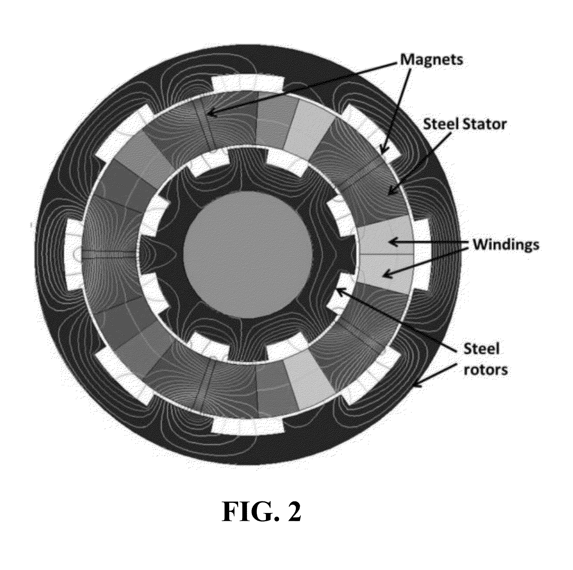
Advantageous machines, such as flux-switching machines (FSMs) are provided. An FSM can be yokeless and can have two rotors, which can be displaced from one another (e.g., by half a pole pitch). An FSM can be a flux-switching permanent magnet machine (FSPMM), and all magnets can be magnetized in the same circumferential direction. FSMs of the subject invention are cost-effective, have high torque density, and can operate well even under fault conditions.
Description
CROSS-REFERENCE TO RELATED APPLICATION[0001]The present application claims the benefit of U.S. Provisional Application Ser. No. 61 / 684,853, filed Aug. 20, 2012, which is hereby incorporated by reference herein in its entirety, including any figures, tables, and drawings.BACKGROUND[0002]Electrical motors are used in a wide variety of applications, such as naval vessels, aircrafts, washing machines, pumps, compressors, and hybrid vehicles. Advanced induction motors, permanent magnet motors, and high temperature superconducting motors are some examples that have been identified to be suitable for propulsion applications. Research has recently focused on permanent magnet motors as a basis for electrical propulsion.[0003]Flux-switching machines belong to the class of doubly-salient permanent magnet (DPSM) machines but have not been traditionally used in the industry. Instead, surface-mounted permanent magnet or interior permanent magnet machines have been used. Existing flux-switching ma...
Claims
Login to View More Application Information
Patent Timeline
 Patent Type & AuthorityApplications(United States)
IPC IPC(8): H02K1/24H02K15/03H02K16/02
CPCH02K1/246H02K15/03H02K16/02H02K21/44Y10T29/49012Y02E10/72H02K21/04H02K1/17
InventorGANDHI, ARUNPARSA, LEILA
OwnerRENESSELAER POLYTECHNIC INST