
Method for driving touch sensor to achieve faster sensor settling

a technology for touch sensors and sensors, applied in the direction of instruments, electric digital data processing, computing, etc., can solve the problems of long settling time and limited waveform frequency, and achieve the effect of reducing the amount of time required for a load to settle and reducing the settling tim

Active Publication Date: 2014-02-20
SYNAPTICS INC
View PDF3 Cites 30 Cited by
  • Summary
  • Abstract
  • Description
  • Claims
  • Application Information

AI Technical Summary

Benefits of technology

The patent is about a method to make electronic devices such as displays or sensors settle faster when being driven. This is done by using multiple voltage levels, including a boosted voltage. This helps to reduce the time needed for the device to fully stabilize and become ready for use.

Problems solved by technology

The frequency of the waveform, however, may be limited because it is necessary to provide a sensing cycle long enough to allow the transmitter electrode to “settle” to a desired value.
However, long settling times may be undesirable due to noise and system performance which may require operating an electronic device at high frequencies.

Method used


Image

  • Method for driving touch sensor to achieve faster sensor settling
  • Method for driving touch sensor to achieve faster sensor settling
  • Method for driving touch sensor to achieve faster sensor settling

Examples


Embodiment Construction

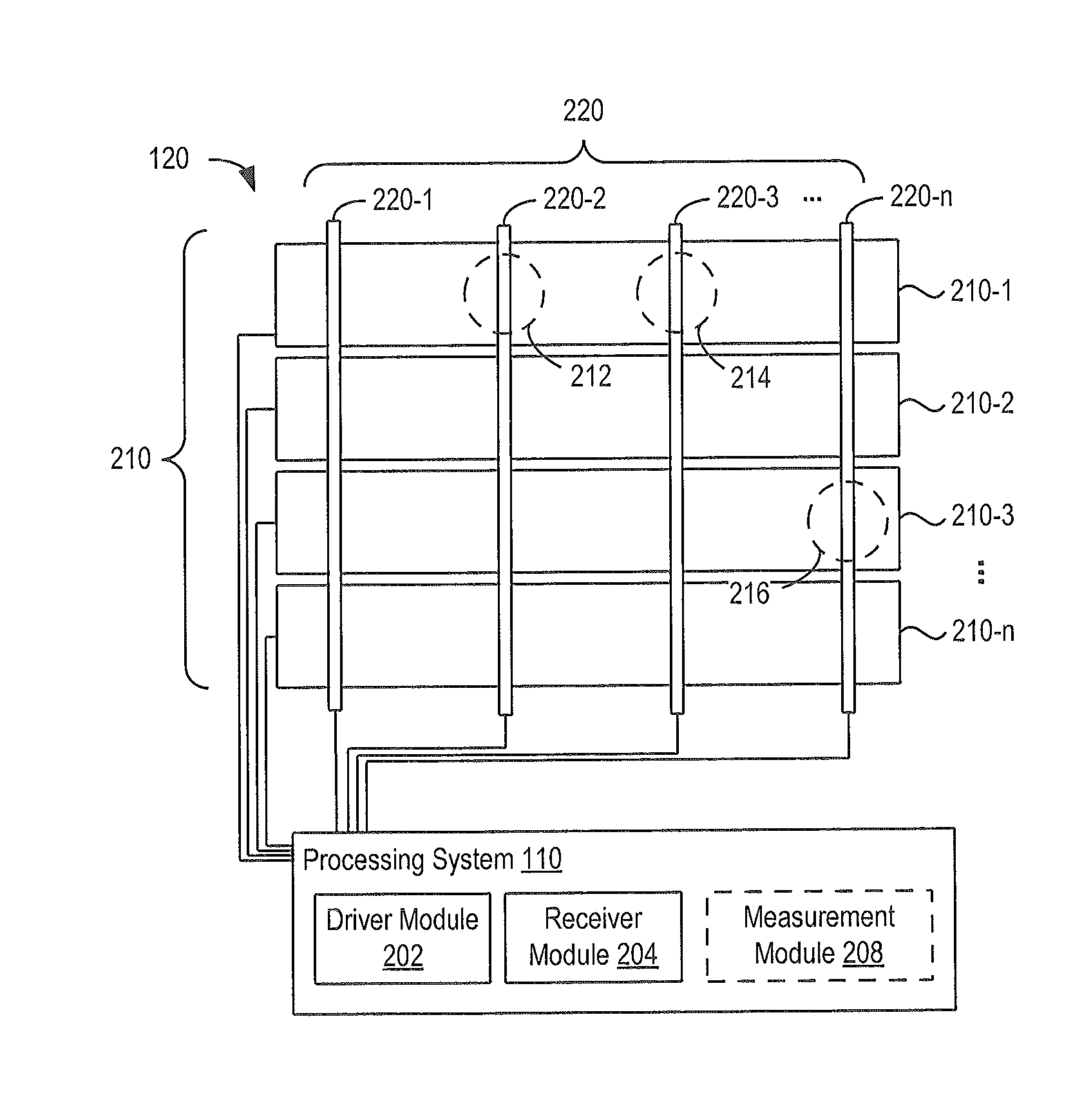
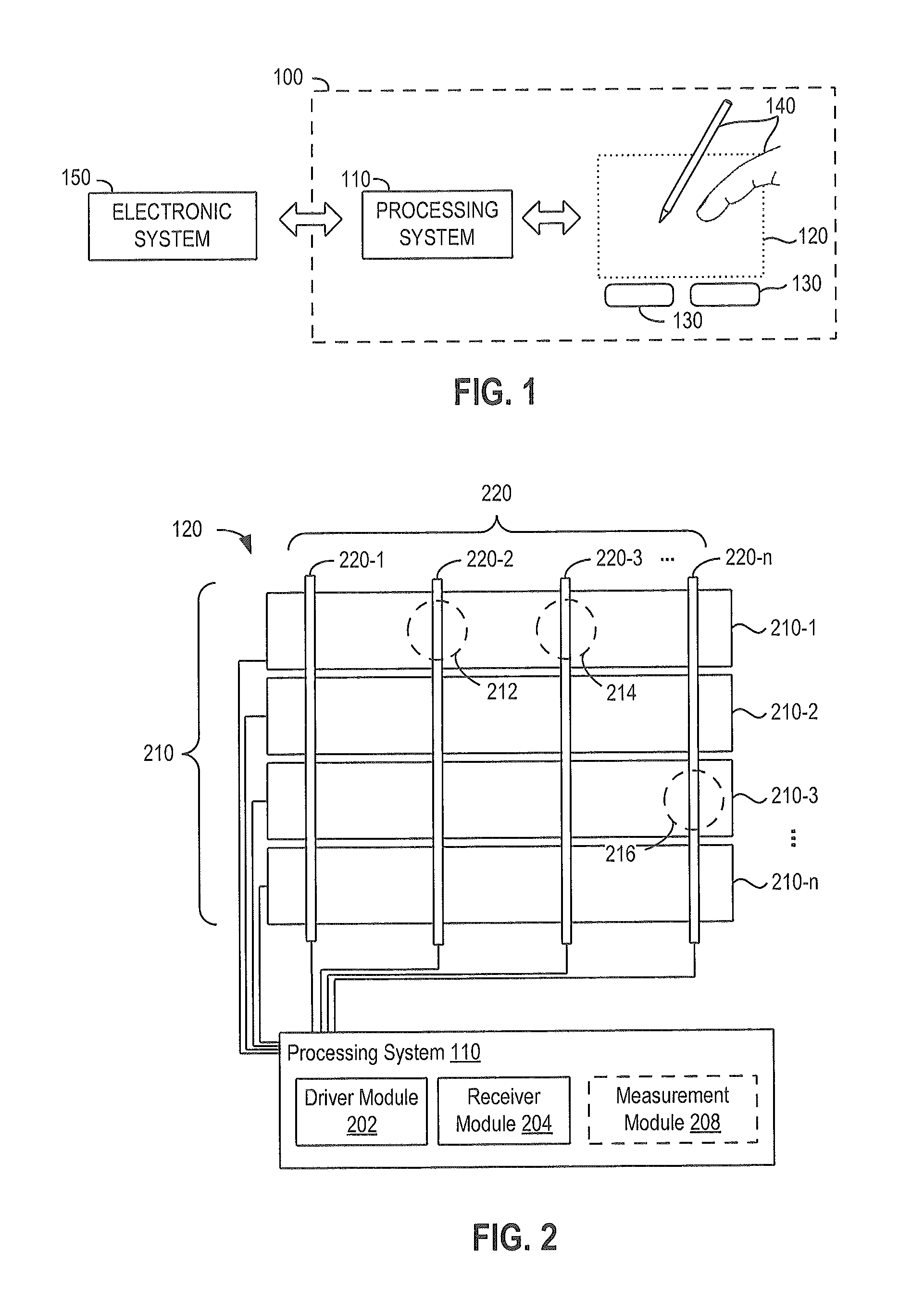
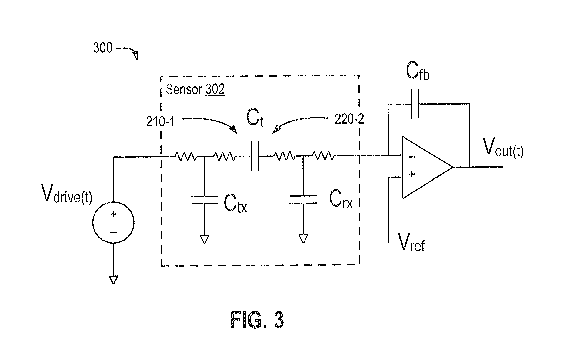
[0021]Embodiments of the present invention describe an approach for driving a capacitive sensor using a driving signal having multiple levels. The multi-level drive scheme decreases the time required for the settling of the capacitive sensor, thereby enabling an increased sensing frequency (for a given settling requirement). Conventional driving techniques use two levels; a high and low level producing a square-wave. The sensing cycle duration is constrained to be long enough to allow the capacitive sensor to settle to some level (e.g., within 95% of the target level). As sensor become thinner and larger, and design requirements become more extreme (requiring smaller pitch), settling behavior is becoming a more important factor. Lower sensing frequency leads to degradation in the noise performance. Accordingly, embodiments of the present invention provide a technique for increasing the sensing frequency that leads to significant gains in capacitive sensor performance.

[0022]FIG. 1 is...


PUM


Abstract

A method and system for driving capacitive pixels in a touch sensor device using a multi-level drive scheme. The drive scheme includes driving a transmitter electrode with a boosted voltage for a first period, and driving the transmitter electrode with a second voltage for a second period. The multi-level transmitter signal is determined based on different settling responses associated with the capacitive pixels of the touch sensor device.

Description

CROSS-REFERENCE TO RELATED APPLICATIONS[0001]This application claims benefit of U.S. provisional patent application Ser. No. 61 / 683,173, filed Aug. 14, 2012, entitled “Method and Apparatus for Fast Settling,” which is herein incorporated by reference.BACKGROUND OF THE INVENTION[0002]1. Field of the Invention[0003]Embodiments of the present invention generally relate to driving loads in electronic devices, or more specifically, driving a transmitter signal in a capacitive sensing device.[0004]2. Description of Related Art[0005]Input devices including proximity sensor devices (also commonly called touchpads or touch sensor devices) are widely used in a variety of electronic systems. A proximity sensor device typically includes a sensing region, often demarked by a surface, in which the proximity sensor device determines the presence, location and / or motion of one or more input objects. Proximity sensor devices may be used to provide interfaces for the electronic system. For example, p...

Claims


Application Information

Patent Timeline
Patent Type & Authority Applications(United States)
IPC IPC(8): G06F3/044
CPCG06F3/044G06F3/0416G09G3/3688G06F3/0445G06F3/0446G06F3/04166G06F2203/04111
Inventor SHEPELEV, PETRSCHWARTZ, ADAM
Owner SYNAPTICS INC
Learn More