Eureka AIR delivers breakthrough ideas for toughest innovation challenges, trusted by R&D personnel around the world.

Connector

Active Publication Date: 2014-02-20
HOSIDEN CORP
View PDF5 Cites 6 Cited by
  • Summary
  • Abstract
  • Description
  • Claims
  • Application Information

AI Technical Summary

Benefits of technology

The present invention provides a connector with improved crosstalk performance and EMI performance. The connector includes a ground terminal with a movable contact portion that easily and reliably comes into contact with the ground contact portion of the second contact. The ground wire is connected to the second contact through the cover member, placing them under the same potential (ground potential) and improving the EMI performance and transmission performance of the connector. The shell of the connector may also have a cover connecting portion to reliably render its potential to the ground potential.

Problems solved by technology

Accordingly, when a plurality of contacts are to be arranged in such a manner that the U-shaped ends thereof are disposed in a row, the width of the connector will become greater than the thickness of the cable disadvantageously.
However, in the case of the above-described layout of the contacts in the connector disclosed in the Japanese Unexamined Patent Application Publication No. 2008-084799, there is the risk of deterioration in the transmission performance such as an intra pair skew, a differential impedance, etc.
Further, in the case of the arrangement eliminating a contact(s) other than those required for signal transmission from the connector, there is the risk of deterioration in the transmission performance such as a crosstalk, etc.

Method used


Image

  • Connector
  • Connector
  • Connector

Examples


Embodiment Construction

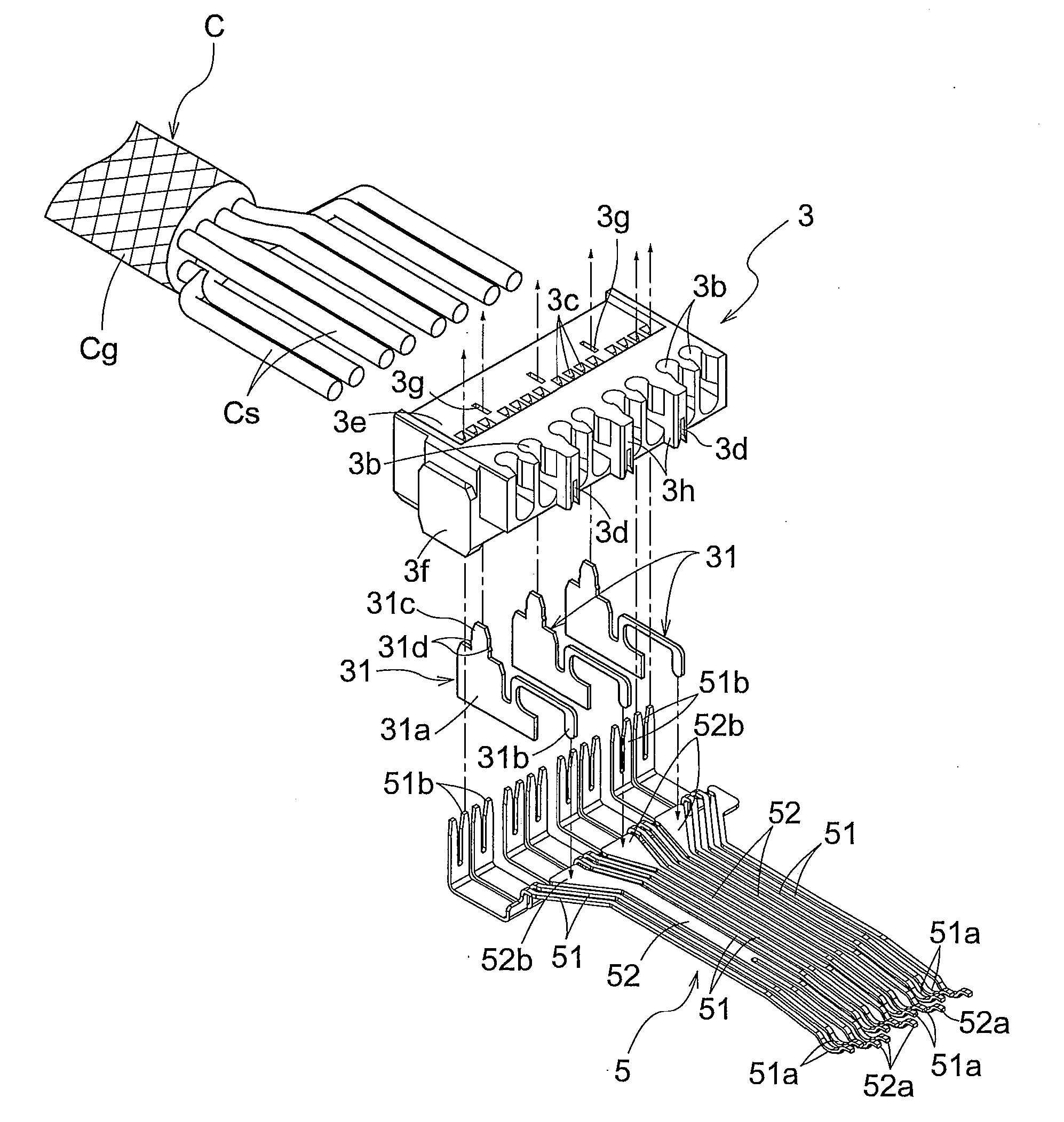
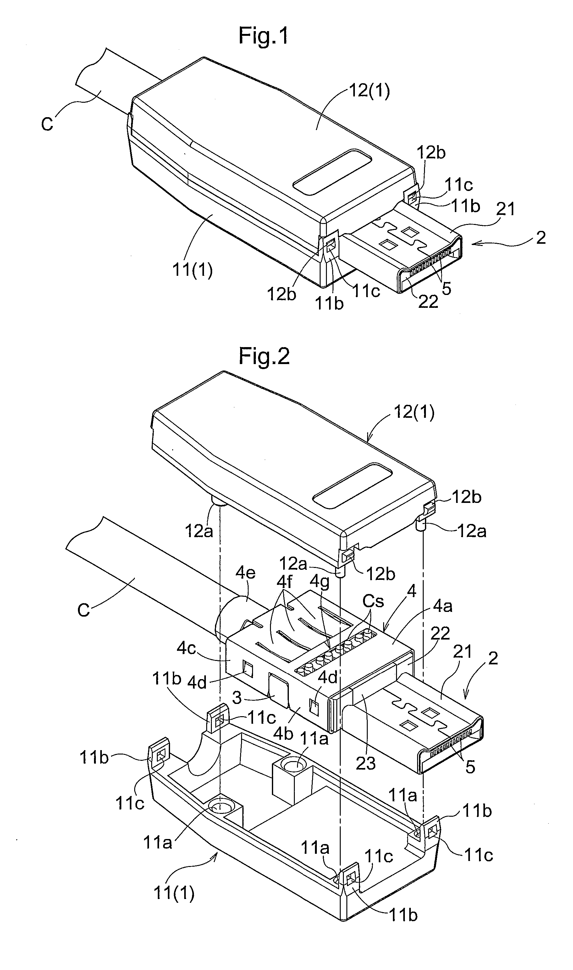
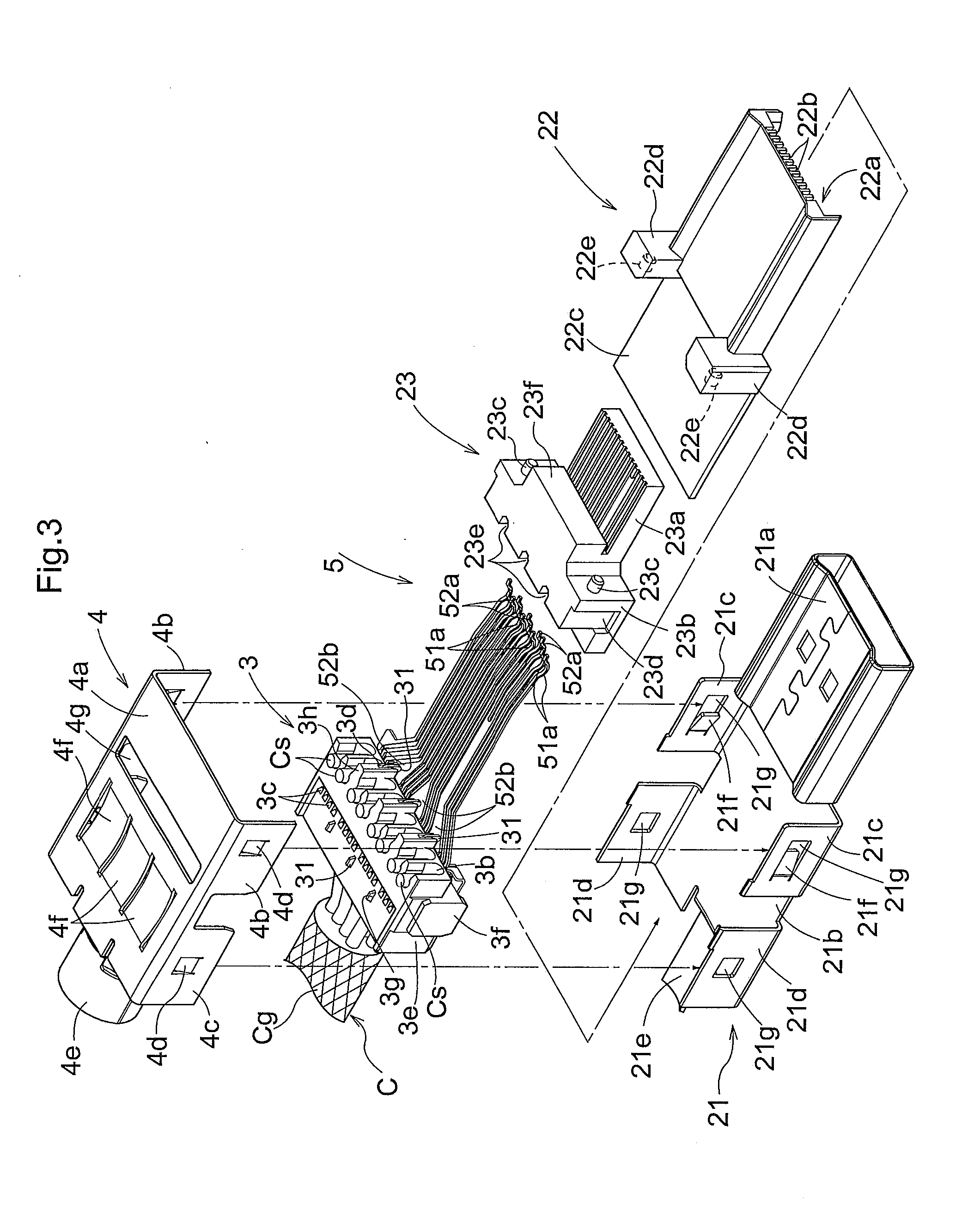
[0042]Next, with reference to the accompanying drawings, an embodiment of the connector according to the present invention will be described. FIG. 1, FIG. 2 and FIG. 3 are a perspective view, an exploded perspective view and a more detailed exploded perspective view showing the connector according to the present invention. As shown in FIG. 1 and FIG. 2, the connector 1 includes a case 1 which is formed of a first case 11 and a second case 12 that are formed of an insulator such as a resin. To one end of the case 1, there is inserted a cable C including a plurality of electric wires sheathed together. Incidentally, in this embodiment, the cable C is provided as a coaxial cable, a plurality of signal wires Cs are sheathed or covered with a conductor such as polyethylene, and the exterior of the conductor is covered with a braided wire acting as a ground wire Cg and this ground wire Cg is covered with an insulator such as vinyl.

[0043]Further, from the other end of the case 1, there is ...


PUM


Abstract

A connector includes a plurality of first contacts and a plurality of second contacts. Each first contact includes a first movable contact portion and a wire connecting portion having a greater width than the width of the first movable portion and connected to a wire. Each second contact is shorter than the first contact and includes a second movable contact portion and a ground contact portion which is not in direct contact with the wire. A contact accommodating member accommodates the first contacts and the second contacts in juxtaposition with each other in such a manner that the wire-side ends of the second contacts are positioned closer to an inserted portion than the wire connecting portions of the first contacts. A guide member includes a ground terminal which comes into contact with the ground contact portion of the second contact.

Description

BACKGROUND OF THE INVENTION[0001]1. Field of the Invention[0002]The present invention relates to a connector for connecting a cable having a plurality of wires to a connection target.[0003]2. Description of the Related Art[0004]A connector for connecting a cable having a plurality of wires to a connection target accommodates therein terminal plates (contacts) corresponding to the wires. The wires and the contacts can be connected to each other by soldering, IDC (Insulation Displacement Contact), etc.[0005]In the case of IDC, the end of a contact to be connected to a wire is formed in U-shape having a recess for clamping the wire therein. For this reason, the U-shaped end of the contact has a width greater than the thickness of the wire. Accordingly, when a plurality of contacts are to be arranged in such a manner that the U-shaped ends thereof are disposed in a row, the width of the connector will become greater than the thickness of the cable disadvantageously.[0006]In an attempt t...

Claims


Application Information

Patent Timeline
IPC IPC(8): H01R13/652
CPCH01R13/652H01R13/6471H01R13/6591H01R13/6597H01R13/648H01R13/58
Inventor KAWAKAMI, YUTA
Owner HOSIDEN CORP
Why Eureka
Eureka Blog
Learn More