
Thermotherapy Device

Inactive Publication Date: 2008-10-30
KITANAKA MICHIKO
View PDF8 Cites 4 Cited by
  • Summary
  • Abstract
  • Description
  • Claims
  • Application Information

AI Technical Summary

Benefits of technology

[0010]With a thermotherapy device having such a configuration of the present invention, by holding the housing with hand or with an equipment to be described hereinafter in such a way that the heat radiation opening of the housing is directed toward the skin around the affected part and by supplying power to the electric heater with the use of the controller, whole of the rod-like electric heater with the leading end thereof being directed toward the heat radiation opening, warms up the air inside the cup-like housing to make convection of the air, and the heat is transmitted onto the skin by convection and also by radiation from the leading end of the electric heater. The affected part on the skin or inside the body under the skin can thus be heated continuously.
[0020]The thermotherapy device of the present invention is preferably provided with a mounting fixture, such as a belt having a hook and loop fastener for adjusting the length or changing the form, for fixing the heat radiation opening of the housing around the affected part. In this manner, there being no need for holding the housing by hand during thermotherapy, the burden on the patient can further be alleviated, and the housing can always be fixed on an accurate position around the affected part each time of repeated thermotherapeutic treatments. Effectiveness of treatment can thus be improved.

Problems solved by technology

However, as for this heat supply device, troublesome replacement of the combustion rod and handling of combustion ash are needed as the combustion rod is consumed.
Further, there is a danger of burn injury or fire disaster if the device is used, for example, in bed or blanket.
In addition, the electric fan being large and heavy, it is difficult to expose for a long time the skin around the affected part to a warm air if the device is carried in hand.
Further, the device is not provided with a function of controlling the amount heat generation.
Thus, for safety reasons, treatment is only possible to such an extent as to slightly warm up the ski, and there is difficulty in providing a treatment with a high temperature sufficient and effective for e.g. treatment of cancer.

Method used


Image

  • Thermotherapy Device
  • Thermotherapy Device
  • Thermotherapy Device

Examples


Embodiment Construction

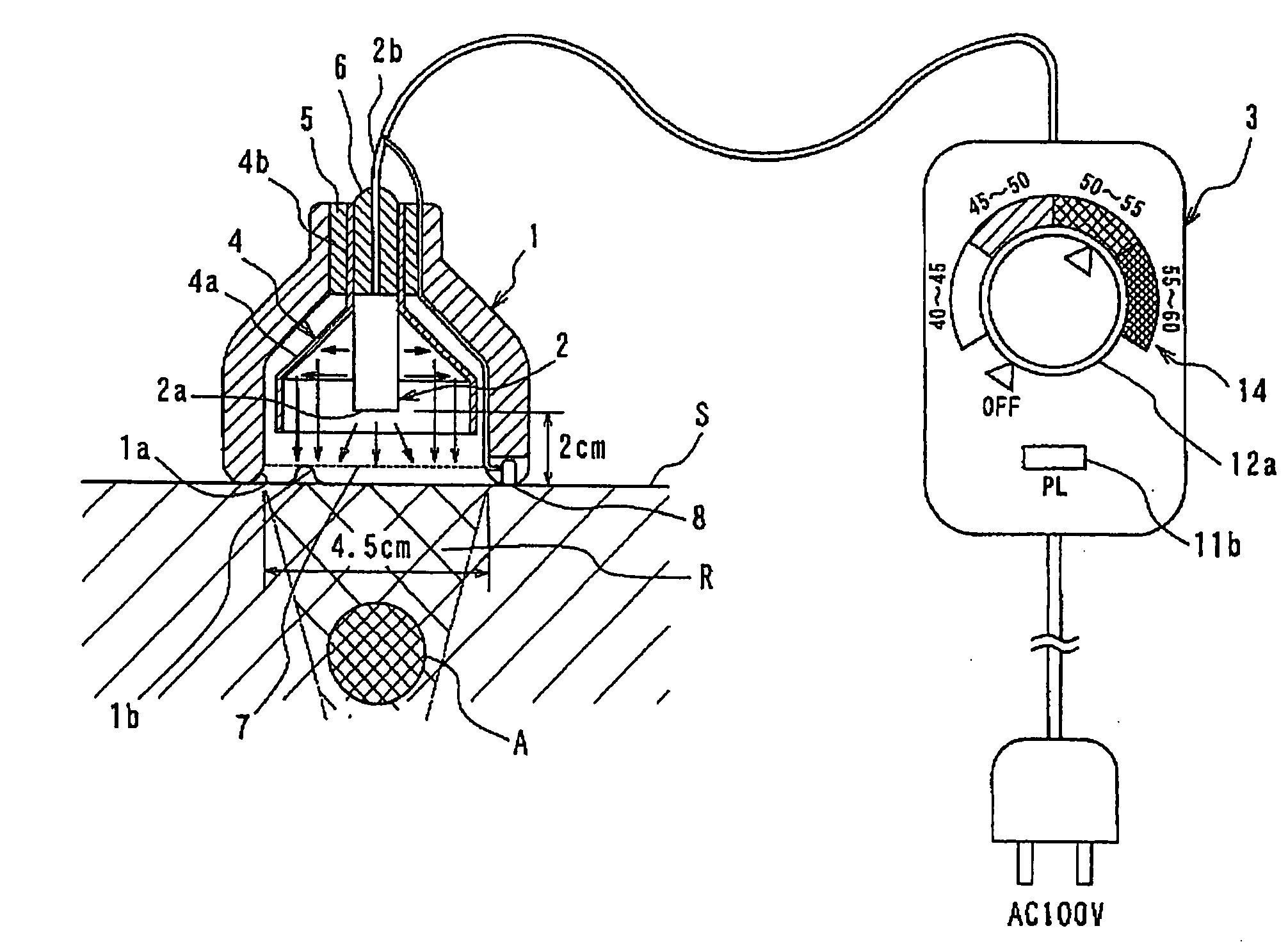
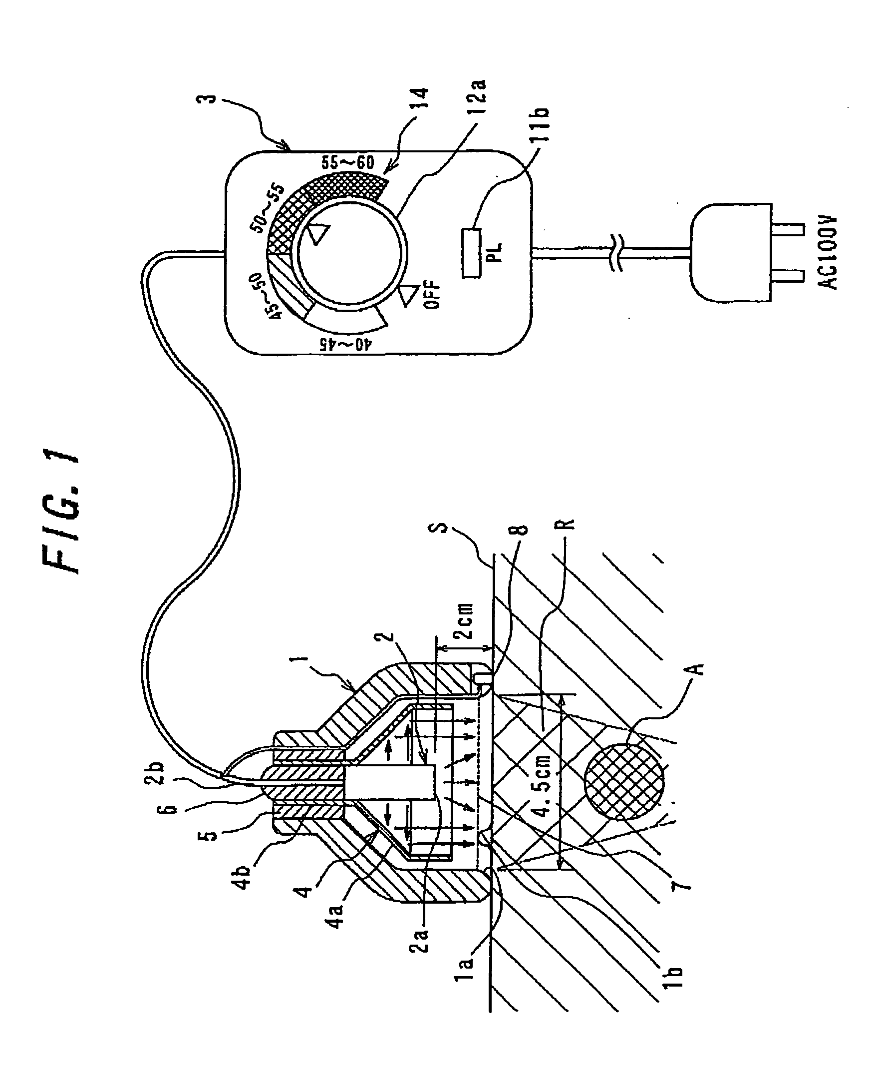
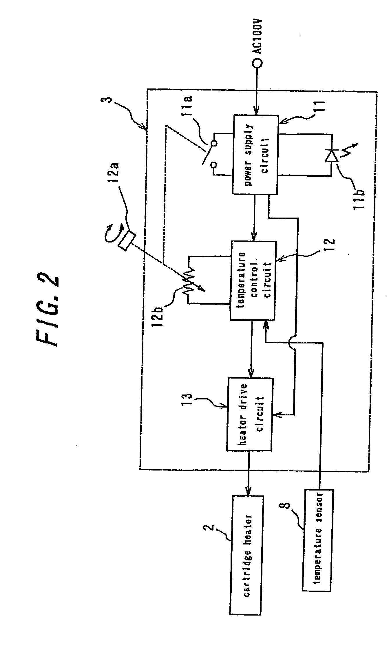
[0026]The preferred embodiments of the present invention will described hereinafter with reference to figures. FIG. 1 is a cross-sectional view showing an embodiment of the thermotherapy device of the present invention, in which the device is being used in such a way as to be attached firmly onto the skin around the affected part. The thermotherapy device according to the present embodiment comprises a cup-like housing 1 having at the fore thereof (at the bottom in FIG. 1) a heat radiation opening 1a, a cartridge heater 2 having an approximate diameter of 9 mm and an approximate length of 27 mm (for example, a FIREROD manufactured by Watlow Japan Co., Ltd.) as a rod-like electric heater contained in the housing in such a way that the leading end 2a thereof is directed toward the heat radiation opening 1a and a controller 3 for supplying power to the cartridge heater 2 and controlling the amount of heat generation from the cartridge heater 2.

[0027]The housing 1 is made of wood (white...


PUM


Abstract

A thermotherapy device comprises a cup-like housing (1) having a heat radiation opening (1a), a rod-like electric heater (2) contained in the housing (1) with the leading end thereof being directed toward the heat radiation opening (1a), and a controller (3) for supplying power to the electric heater (2) and controlling the amount of heat generation from the electric heater (2). Since the electric heater (2) is employed, replacement of a combustion rod and handling of combustion ash are not required, and the thermotherapy device can be used even in bed. Moreover, power is supplied to the electric heater (2) while regulating the amount of heat generation by means of controller (3). Accordingly, the skin (S) can be heated in safety to a high temperature of 55 to 60 degrees C., and an affected part (A) located on or under the skin (S) can be exposed to a sufficiently high temperature for treatment of cancer.

Description

FIELD OF THE INVENTION[0001]The present invention relates to a thermotherapy device for an effective treatment of diseases including cancer, by heating an affected part on the skin or inside the body under the skin.BACKGROUND OF THE INVENTION[0002]As a device for a treatment of a disease by heating an affected part on or under the skin is known, for example, a heat supply device comprising as a heat source a combustion rod (see Japanese, Utility Model Application Laid-Open No. S63-103618).[0003]This heat supply device comprises a combustion rod composed of moxa caked into the shape of a rod and supported inside a support tube. The air inside the support tube is warmed up by combustion at the tip of the combustion rod to become a warm air and to be blown onto the skin around the affected part by an electric fan.[0004]However, as for this heat supply device, troublesome replacement of the combustion rod and handling of combustion ash are needed as the combustion rod is consumed. Furth...

Claims


Application Information

Patent Timeline
IPC IPC(8): A61F7/00A61F7/02A61F7/12
CPCA61F7/007A61F2007/0086
Inventor KITANAKA, KATSUMI
Owner KITANAKA MICHIKO
Features
  • Generate Ideas
  • Intellectual Property
  • Life Sciences
  • Materials
  • Tech Scout
  • Unparalleled Data Quality
  • Higher Quality Content
  • 60% Fewer Hallucinations
Learn More