Ladder balance adjusting apparatus

a technology of adjusting apparatus and ladder, which is applied in the direction of scaffold accessories, construction, building aids, etc., can solve the problems of inconvenient use, low applicability and popularity of adjustment devices, and long time consumption, so as to improve the practicality of products.

Inactive Publication Date: 2014-02-27
LU WEN HUA
View PDF1 Cites 11 Cited by
  • Summary
  • Abstract
  • Description
  • Claims
  • Application Information

AI Technical Summary

Benefits of technology

[0006]In view of the problems of the prior art, it is a primary objective of the present invention to provide a ladder balance adjusting apparatus with a two-piece assembly to lower the production cost and decrease the level of difficulty for installation and disassembly, so that the apparatus can be used extensively and universally.
[0007]To achieve the foregoing objective, the present invention provides a ladder balance adjusting apparatus applied and installed to an n-shaped ladder leg of a foldable ladder, for supporting and adjusting the height of the ladder leg to securely install the foldable ladder, comprising: an assembly, a base cover, a fixing element, a base cup, a stand rod, a foot disc and a control element, and the stand rod is a circular rod with a plurality of first threads formed on a surface of the stand rod and a connection portion of a sphere disposed at an end of the stand rod and embedded into the foot disc in a circular shape, and the base cup, the fixing element, the base cover and the assembly are installed at the other end of the stand rod; and the base cover is a tapered hollow cone fixed to the assembly and having a containing chamber formed therein for receiving the fixing element; the base cup is covered by the base cover and the fixing element is sealed into the containing chamber; the control element is having a gasket, a pair of first springs, a pull rod and a pull string, and the pull string is coupled to the pull rod, and the pull rod is pivotally coupled to the bottom of the base cup, and the pair of first springs are having an end coupled to the pull rod and the other end coupled to a side of the gasket, and the other side of the gasket is abutting the fixing element; the fixing element is comprising three petal pieces disposed around the stand rod and connected to form a hollow cone, and an external wall of each of the petal pieces is an oblique conical surface, and a plurality of second threads are formed at a lower edge of an internal wall of each of the petal pieces, such that when the containing chamber compresses the oblique conical surfaces to fold the petal pieces, the second threads are engaged with the first threads, characterized in that the assembly comprises a first component and a second component, and the second component has a side and a bottom to form an L-shaped structure, and the bottom of the second component is fixed to the base cover and has a through hole formed at the center of the bottom of the second component for receiving the stand rod, and after the ladder leg is placed between the first component and the second component and locked by a plurality of locking elements, so that the first component and the second component clamp and fix the ladder leg. Therefore, the two-piece assembly allows the present invention to adapt ladder legs of different sizes, so as to improve the applicability of the product significantly.
[0009]Through the principle of mechanics of the control knob and the second spring, the fixing element can be engaged to the stand rod with an adjusted height to improve the practicality of the product.

Problems solved by technology

The conventional adjusting procedure by pulling and turning repeatedly not only incurs an inconvenient use, but also takes much time and fails to meet the required efficiency.
However, the aforementioned adjusting device is incompatible to some of the mechanical devices due to the limitation of the fixed structural dimensions and shape of the stand 10, so that such adjustment device has low applicability and popularity.
In addition, the fastener 14 comprises of two petal pieces, so that the insufficient engaging area between the stand rods 11 results in an insufficient holding force, and the stand rods 11 may slide or fall down easily to give rise to a safety issue.
The movable latch 13 abuts the fastener 14 for long and may be worn out or damage to affect the adjusting effect.

Method used


Image

  • Ladder balance adjusting apparatus
  • Ladder balance adjusting apparatus
  • Ladder balance adjusting apparatus

Examples


Embodiment Construction

[0017]The technical contents of the present invention will become apparent with the detailed description of preferred embodiments and the illustration of related drawings as follows.

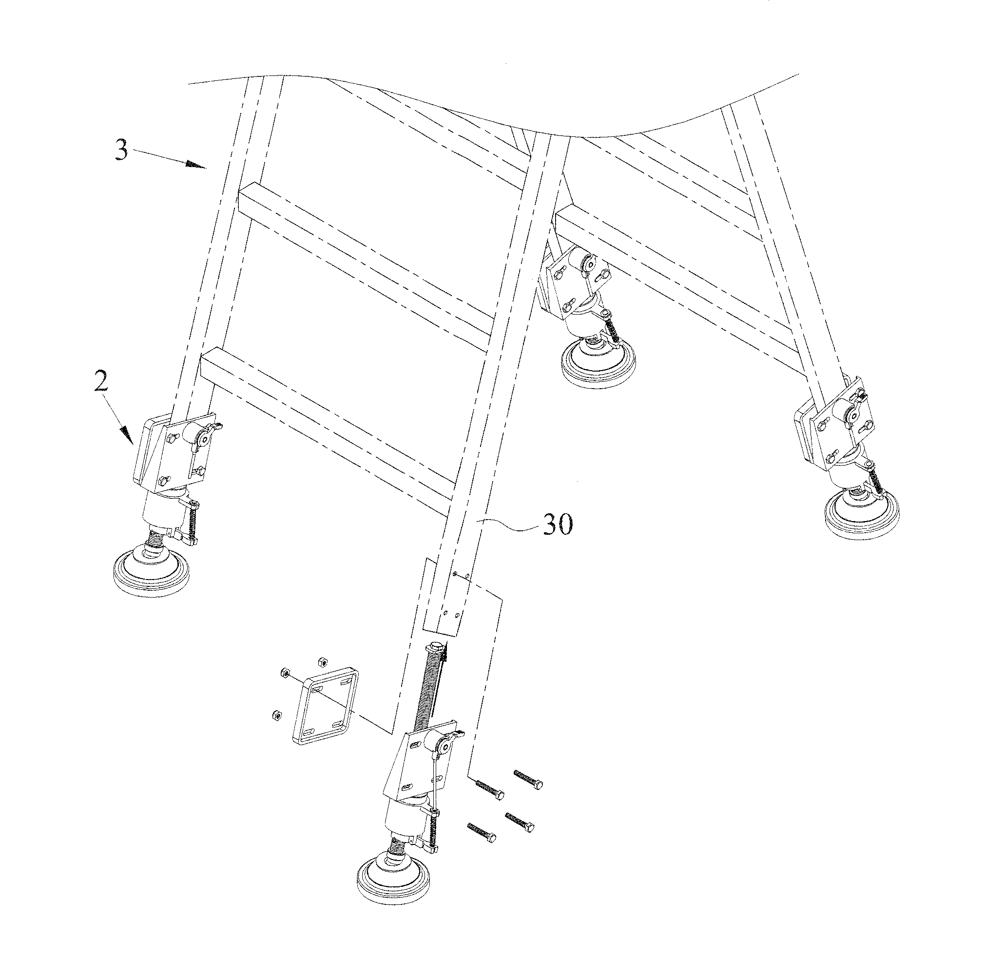
[0018]With reference to FIGS. 3 to 7 for an exploded view, a perspective view, and schematic views of an operation and an application of a preferred embodiment of the present invention, a ladder balance adjusting apparatus 2 is applied for adjusting the height of a foot of a mechanical device such as a ladder, a scaffold, an instrument or a piece of furniture. For example, the ladder balance adjusting apparatus 2 is installed to an n-shaped ladder leg 30 of a foldable ladder 3 to support and adjust the height of the ladder leg 30 and erect the foldable ladder 3 stably. The ladder balance adjusting apparatus 2 comprises an assembly 20, a base cover 21, a fixing element 22, a base cup 23, a stand rod 24, a foot disc 25 and a control element 26, wherein the stand rod 24 is a circular rod having a plurality ...


PUM


Abstract

A ladder balance adjusting apparatus installed on an n-shaped ladder leg includes an assembly, a base cover, a fixing element, a base cup, a stand rod, and a control element. The assembly has a first component and a second component, and the second component has a side and a bottom to form an L-shaped structure, and after the ladder leg is installed between the two components, the ladder leg is locked by a plurality of locking elements. The base cover is coupled to the assembly and the base cup, and the fixing element is built in the base cover, and the stand rod is provided for passing the aforementioned elements to support the ladder leg, and the control element is provided for controlling the fixing element to adjust the height of the ladder leg, and to simplify the manufacturing process of components, the installation and disassembly of the apparatus.

Description

BACKGROUND OF THE INVENTION[0001]1. Field of the Invention[0002]The present invention relates to the technical field of ladder assisting support base or base, in particular to a ladder balance adjusting apparatus featuring a low production cost and simplifying the assembling and disassembling procedures by using a two-piece assembly.[0003]2. Description of the Related Art[0004]In general, an adjusting device simply comprised of a foot pad and a bolt is installed to each foot of a mechanical device to overcome a height difference and improve the stability of a ladder, a scaffold, an instrument or a piece of furniture installed on the ground, and also secure a knob bolt after the height of each foot pad is adjusted. The conventional adjusting procedure by pulling and turning repeatedly not only incurs an inconvenient use, but also takes much time and fails to meet the required efficiency. To overcome the aforementioned problem, R.O.C. Pat. No. TW 1301179 discloses a “Quick stand adjus...

Claims


Application Information

Patent Timeline
Patent Type & Authority Applications(United States)
IPC IPC(8): E06C7/44
CPCE06C7/44
Inventor LU, WEN-HUA
Owner LU WEN HUA
Why Eureka
Try Eureka