LED heat dissipation structure

a technology of heat dissipation structure and led lamp, which is applied in the direction of lighting and heating apparatus, semiconductor devices for light sources, and support devices for lighting and heating. it can solve the problems of lamp overheating or even damage, high assembly cost, and low thermal conduction

Inactive Publication Date: 2014-12-23
SHUNCHI TECH
View PDF5 Cites 1 Cited by
  • Summary
  • Abstract
  • Description
  • Claims
  • Application Information

AI Technical Summary

Benefits of technology

[0005]Therefore, it is a primary objective of the present invention to overcome the aforementioned problems by providing an LED heat dissipation structure with an integrally formed fin structure, so that heat generated by a lamp can be conducted to the outside through the material of this structure, and the heat dissipation effect will not be affected by insufficient precision of mold manufacture and assembling.
[0006]Another objective of the present invention is to achieve the effects of simplifying the structure of the lamp, saving the assembling time, and reducing the level of difficulty of the manufacture to lower the production cost by using the integrally formed fin structure.

Problems solved by technology

If the tightness of the combining surface 71 of the two parts 7 is not up to a standard, the thermal conduction effect will be low, and the lamp may be overheated or even damaged.
On the other hand, the through holes of the second containing slot 73 are provided for containing the electric wires 82, but the electric wires 82 are soft and easy to deform, so that it takes much more time to install the deformed electric wires 82 into the through holes during the installation process, thus incurring a higher assembling cost.

Method used


Image

  • LED heat dissipation structure
  • LED heat dissipation structure
  • LED heat dissipation structure

Examples


Embodiment Construction

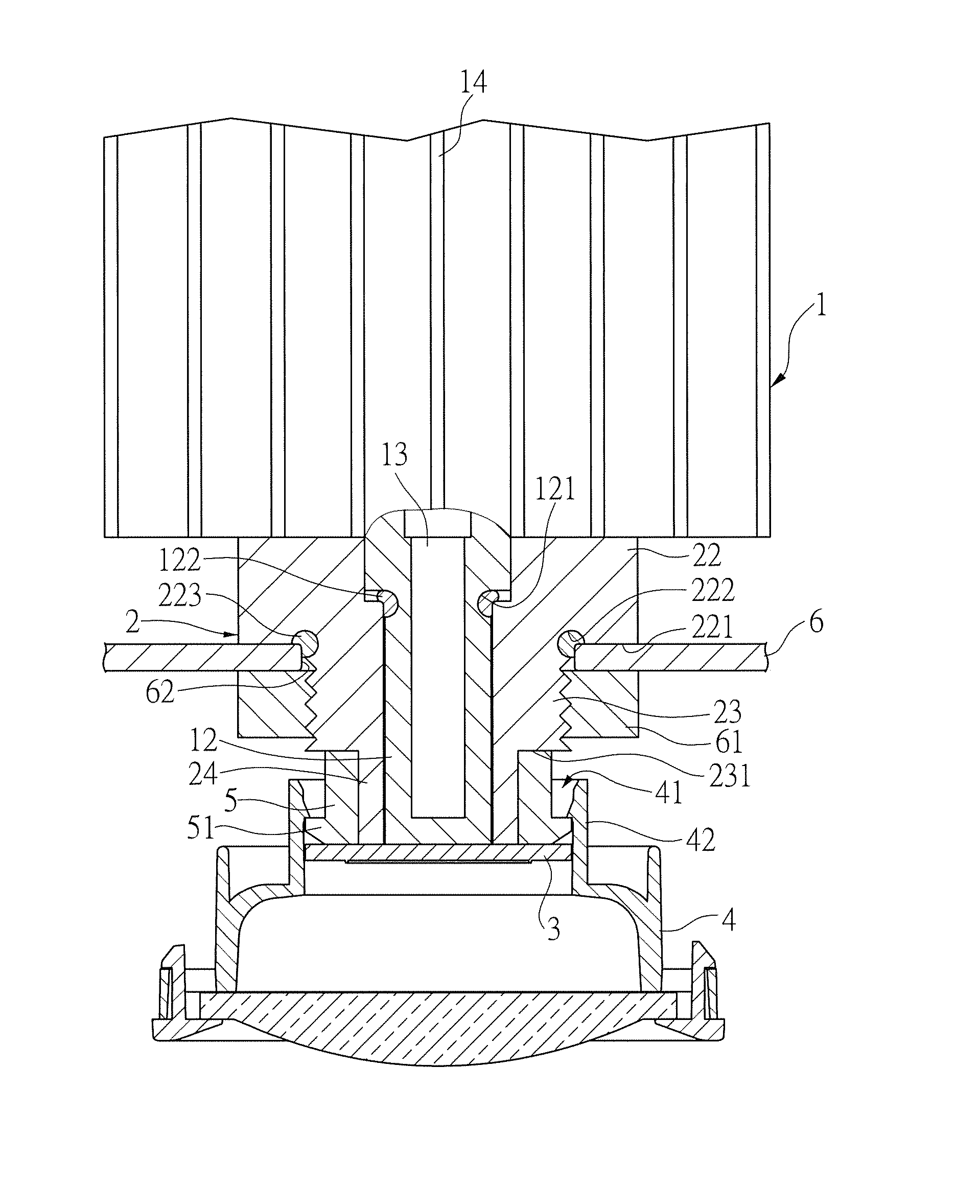
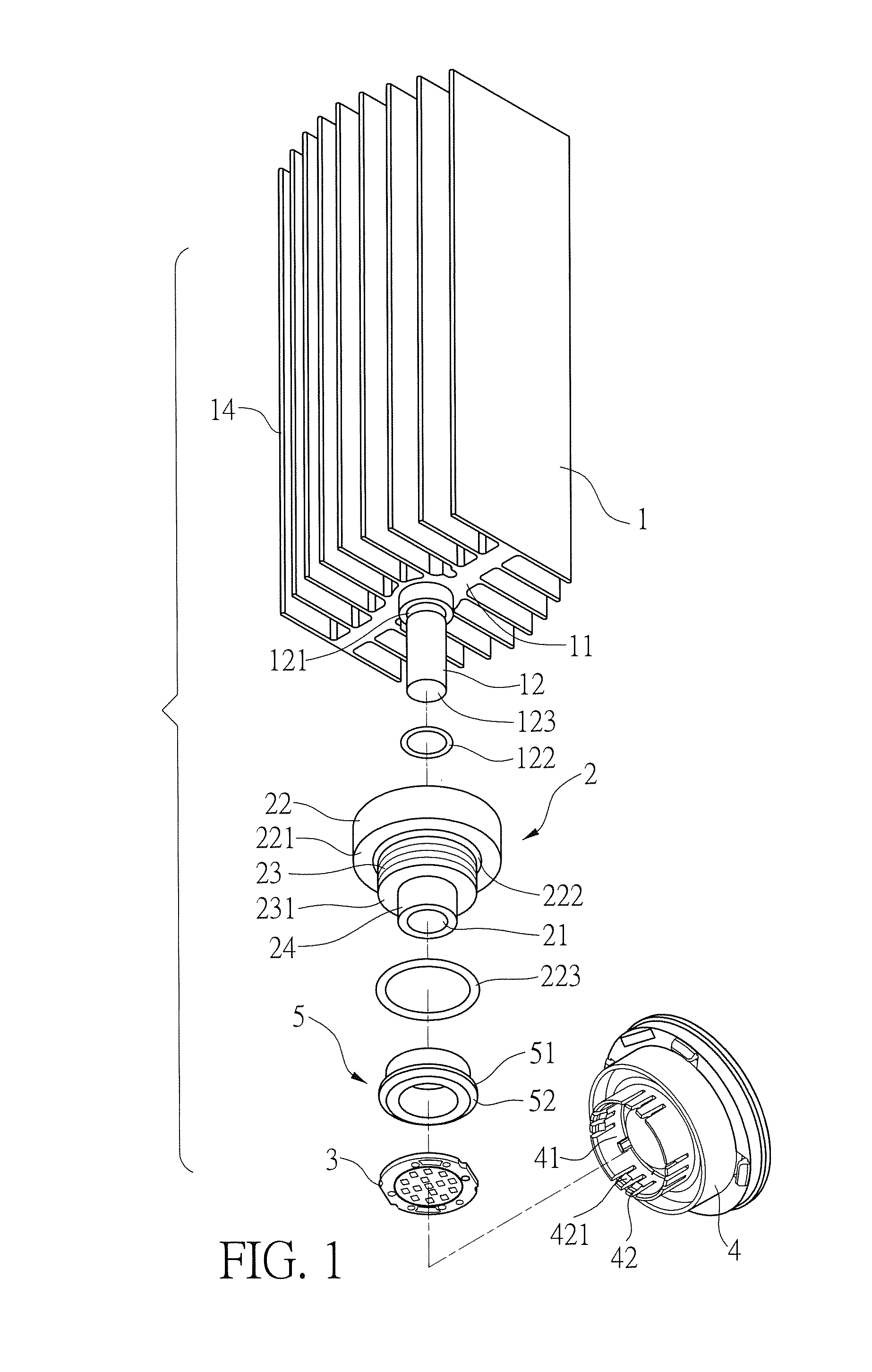
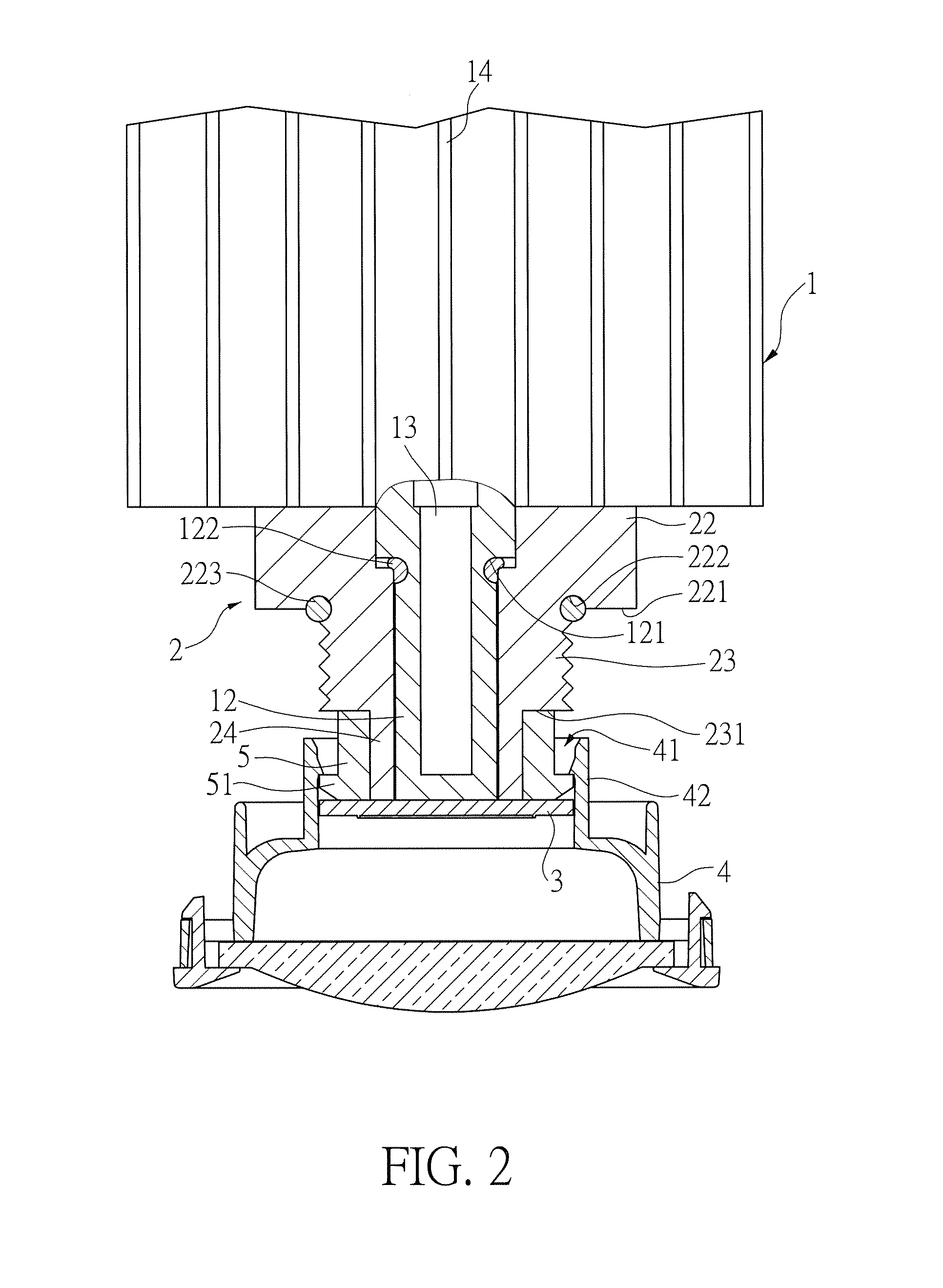
[0014]With reference to FIGS. 1 and 2 for an LED heat dissipation structure of the present invention, the LED heat dissipation structure comprises a heat sink 1 integrally formed in a column shape and having a support surface 11 disposed at an end of the heat sink 1, and a lug 12 axially extended from the support surface 11. The heat sink 1 has a hollow portion 13 disposed therein and axially extended to the lug 12, and a plurality of fins 14 integrally extended from the peripheral side of the heat sink 1, wherein the hollow portion 13 contains a heat dissipating liquid, so that after the liquid absorbs heat, the liquid in the hollow portion 13 is evaporated into a gas. The gas rises due to density, and the heat is dissipated by the heat sink 1 and the fins 14 while the gas is rising, so that the gas can return to its liquid form and drops to the bottom, so as to define a cycle of a heat dissipation process, and the LED heat dissipation structure is called a “light engine device”.

[0...


PUM


Abstract

An LED heat dissipation structure including: a heat sink, with a lug axially extended from an end of the heat sink, a hollow portion disposed inside the heat sink and axially extended to the lug, and a plurality of fins integrally extended from a peripheral side of the heat sink; and a support base, having an axial through hole sheathed on the lug of the heat sink, and an end of the support base abutting the support surface of the heat sink. A semiconductor light emitting module is tightly coupled onto a distal surface at an end of the lug for conducting generated heat to the heat sink, and a mirror mount is pressed against the semiconductor light emitting module and coupled to the support base.

Description

FIELD OF THE INVENTION[0001]The present invention relates to a light emitting diode (LED) lamp, and more particularly to the LED lamp with an integral heat dissipation structure.BACKGROUND OF THE INVENTION[0002]With reference to FIG. 5 for a conventional LED lamp of a light engine device, the LED lamp has a fin structure comprised of two parts 7, wherein a combining surface 71 of the two parts has a first containing slot 72 and a second containing slot 73 integrally and separately formed on both sides of the first containing slot 72, so that there are three through holes provided for containing a heat pipe 81 and electric wires 82 of a semiconductor light emitting module 8. The conventional LED lamp achieves the heat dissipation effect by conducting heat generated by the semiconductor light emitting module 8 through the heat pipe 81 and then dissipated to the outside from a plurality of fins 74.[0003]In the foregoing heat dissipation structure, the heat pipe 81 must be in a tight co...

Claims


Application Information

Patent Timeline
Patent Type & Authority Patents(United States)
IPC IPC(8): F21V17/06H01L33/64F21V17/00F21V29/00
CPCF21V29/006F21V29/2225F21V17/06F21V19/045F21V17/005F21Y2101/02F21K9/30H01L33/642F21V29/004F21V29/77F21K9/20F21Y2115/10F21V19/04
Inventor HUNG, YOU-NAN
Owner SHUNCHI TECH
Why Eureka
Try Eureka