
Counter balancing apparatus for moving-iron bone-conducted sound receiving device

a counter-balancing apparatus and moving iron bone technology, applied in electrical transducers, deaf-aid sets, electrical apparatus, etc., can solve the problems of low transduction efficiency of the sound receiving system, limited application range, and inability to increase the mass of the product, so as to avoid structural deficiencies, increase the effective moving mass of the counter-balancing apparatus, and optimize the space occupied

Active Publication Date: 2016-03-01
SUZHOU YICHUAN TECH CO LTD
View PDF14 Cites 0 Cited by
  • Summary
  • Abstract
  • Description
  • Claims
  • Application Information

AI Technical Summary

Benefits of technology

The split-type design optimizes space usage, increases effective moving mass, and improves vibration output while reducing manufacturing complexity, enabling smaller product size and flexible application for various moving-iron bone-conducted sound receiving devices.

Problems solved by technology

This type of counter balancing apparatus is relatively easy to manufacture and process, however, when it is used in a product of moving-iron bone-conducted sound receiving device, because of the restriction of its external shape, it needs to occupy a lot of internal space of the product, which leads to problems such as too large size of product, and limited range of application, also, because the effective moving mass of the product cannot be increased due to its onefold shape, the transduction efficiency of the sound receiving system can be low and the output vibration level of the corresponding moving-iron bone-conducted sound receiving device can be insufficient.
In brief, counter balancing apparatuses of the prior art generally have the deficiencies of shape redundancy, onefold structure, poor functionality, etc.

Method used


Image

  • Counter balancing apparatus for moving-iron bone-conducted sound receiving device
  • Counter balancing apparatus for moving-iron bone-conducted sound receiving device
  • Counter balancing apparatus for moving-iron bone-conducted sound receiving device

Examples


Embodiment Construction

[0019]The technical solution of the present invention is further described below, in conjunction with appended drawings and preferred embodiments.

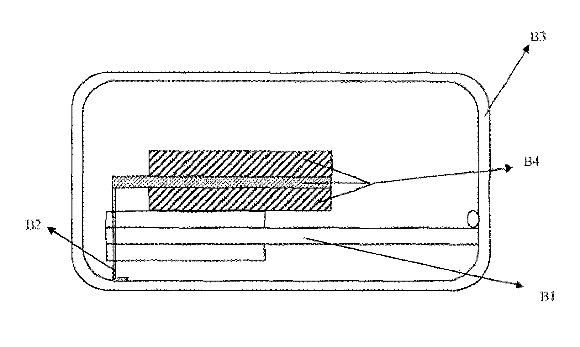
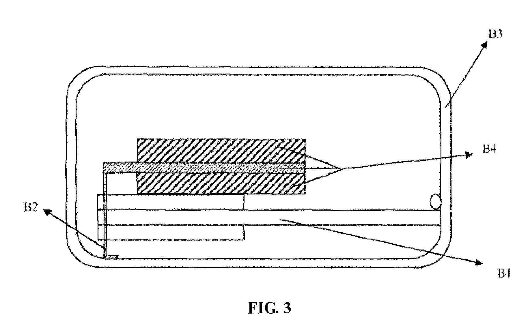
[0020]Referring to FIG. 2 and FIG. 3, the present embodiment involves a counter balancing apparatus B1 for moving-iron bone-conducted sound receiving device, and the counter balancing apparatus B1 comprises a baseboard A1 and counter-balancing blocks A2. The baseboard A1 is configured in a planar structure, with an open notch A3 on its front end; two sheets of counter-balancing blocks A2 are also configured in a planar structure and are provided symmetrically on both sides of the baseboard A1, and an open notch A3 formed on the front end of each of the counter-balancing blocks A2 is aligned with the open notch A3 on the front end of the baseboard A1.

[0021]Preferably, the baseboard A1 and the counter-balancing blocks A2 of the counter balancing apparatus B1 in the present embodiment are bound together by laser welding, i.e. the material adj...


PUM


Abstract

A counter balancing apparatus for moving-iron bone-conducted sound receiving device; the baseboard is configured in a planar structure, with open notch on its front end; two counter-balancing blocks configured in a planar structure and provide symmetry on both sides of the baseboard, and an open notch formed on the front end of each of the counter-balancing blocks aligns with the open notch on the front end of the baseboard. The invention increases effective moving mass of its counter balancing apparatus and optimizes space occupied by its counter balancing apparatus, enhancing transduction efficiency and output vibration level of the corresponding moving-iron bone-conducted sound receiving device; controlling the product size; the baseboard split type design and counter-balancing blocks; reduces difficulty of manufacturing its counter balancing apparatus, and flexibly meets the requirement of moving mass for various moving-iron bone-conducted sound receiving devices by selection of different thickness and shapes of counter-balancing blocks.

Description

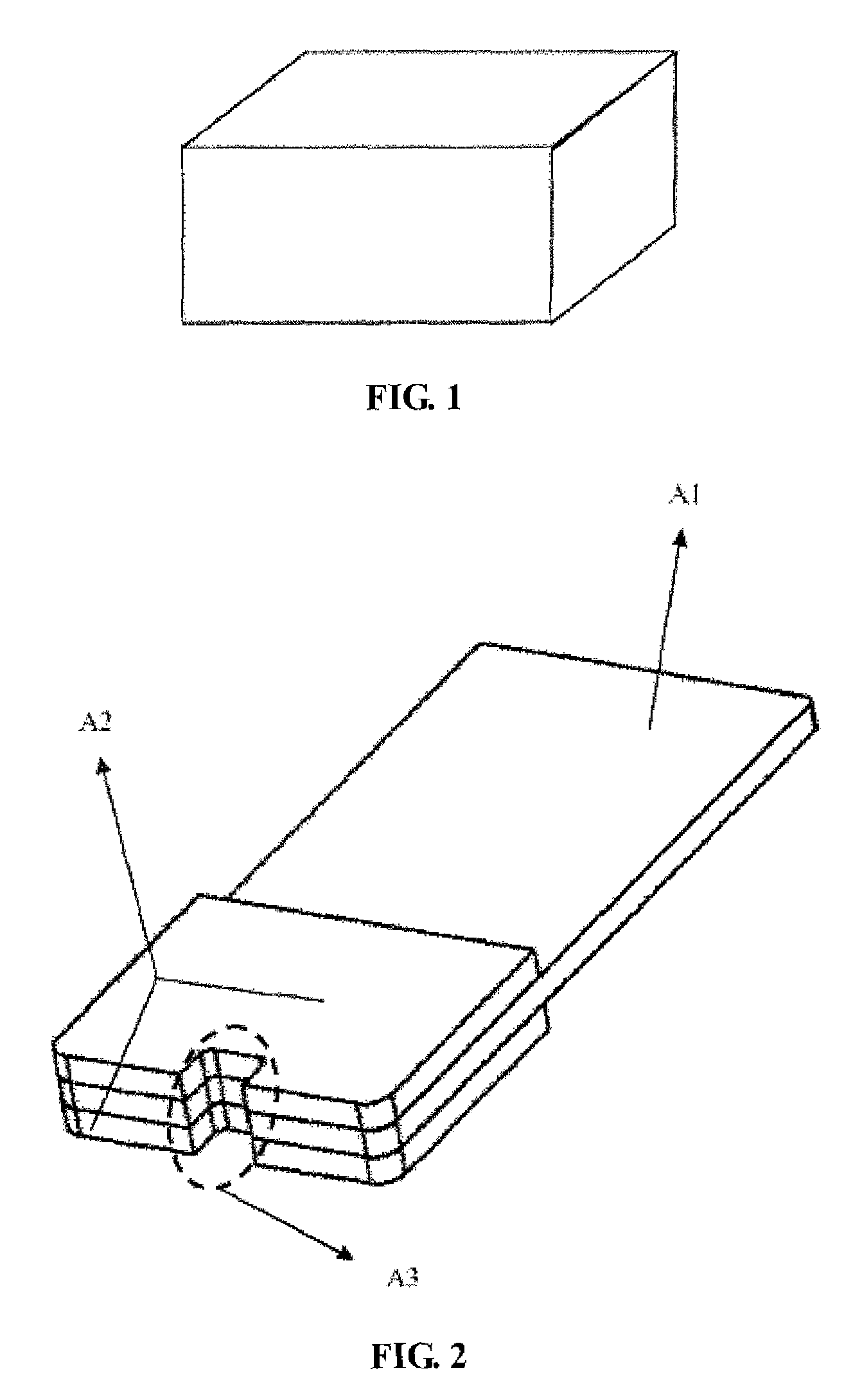
TECHNICAL FIELD[0001]The present invention relates to a vibration conduction and energy transduction device, and particularly relates to a counter balancing apparatus for moving-iron bone-conducted sound receiving device, which pertains to the field of electro-acoustic and micro-mechanics.BACKGROUND OF THE INVENTION[0002]At present, the commercial available counter balancing apparatuses for moving-iron bone-conducted sound receiving device are generally configured in a monoblock metal rectangular solid. This type of counter balancing apparatus is relatively easy to manufacture and process, however, when it is used in a product of moving-iron bone-conducted sound receiving device, because of the restriction of its external shape, it needs to occupy a lot of internal space of the product, which leads to problems such as too large size of product, and limited range of application, also, because the effective moving mass of the product cannot be increased due to its onefold shape, the t...

Claims


Application Information

Patent Timeline
Patent Type & Authority Patents(United States)
IPC IPC(8): H04R25/00H04R1/46H04R11/04
CPCH04R1/46H04R11/04
Inventor ZHOU, WEILI, LIANG
Owner SUZHOU YICHUAN TECH CO LTD
Learn More