Electrostatic Carrier Tray

a technology of electrostatic carrier and carrier tray, which is applied in the direction of electrostatic holding device, basic electric elements, electric apparatus, etc., can solve the problem of no effective and easy way to move electronic substrates

Active Publication Date: 2014-02-27
DIABLO CAPITAL INC
View PDF5 Cites 1 Cited by
  • Summary
  • Abstract
  • Description
  • Claims
  • Application Information

AI Technical Summary

Problems solved by technology

Currently, there is no effective and easy way to ...

Method used


Image

  • Electrostatic Carrier Tray
  • Electrostatic Carrier Tray
  • Electrostatic Carrier Tray

Examples


Embodiment Construction

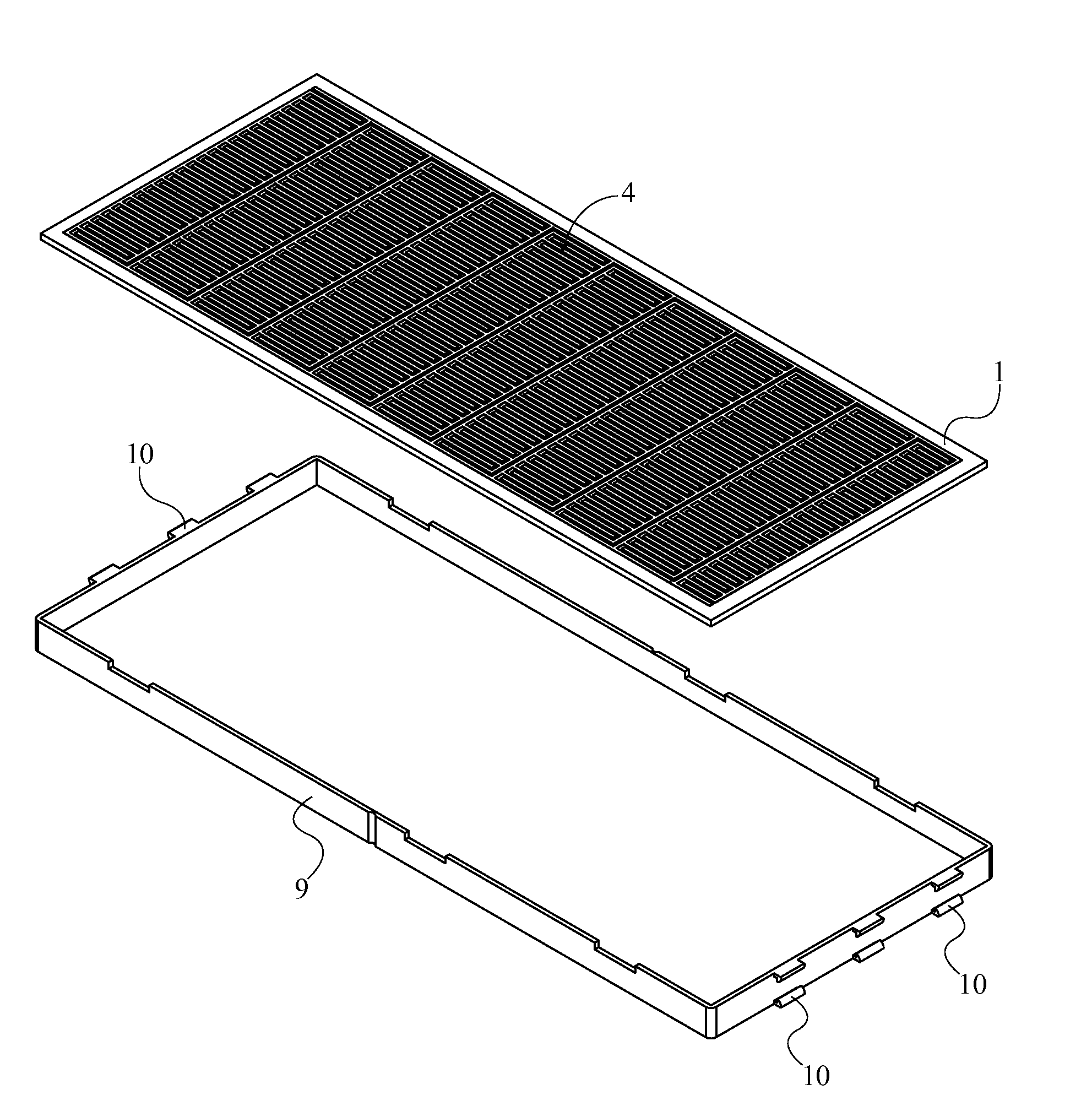
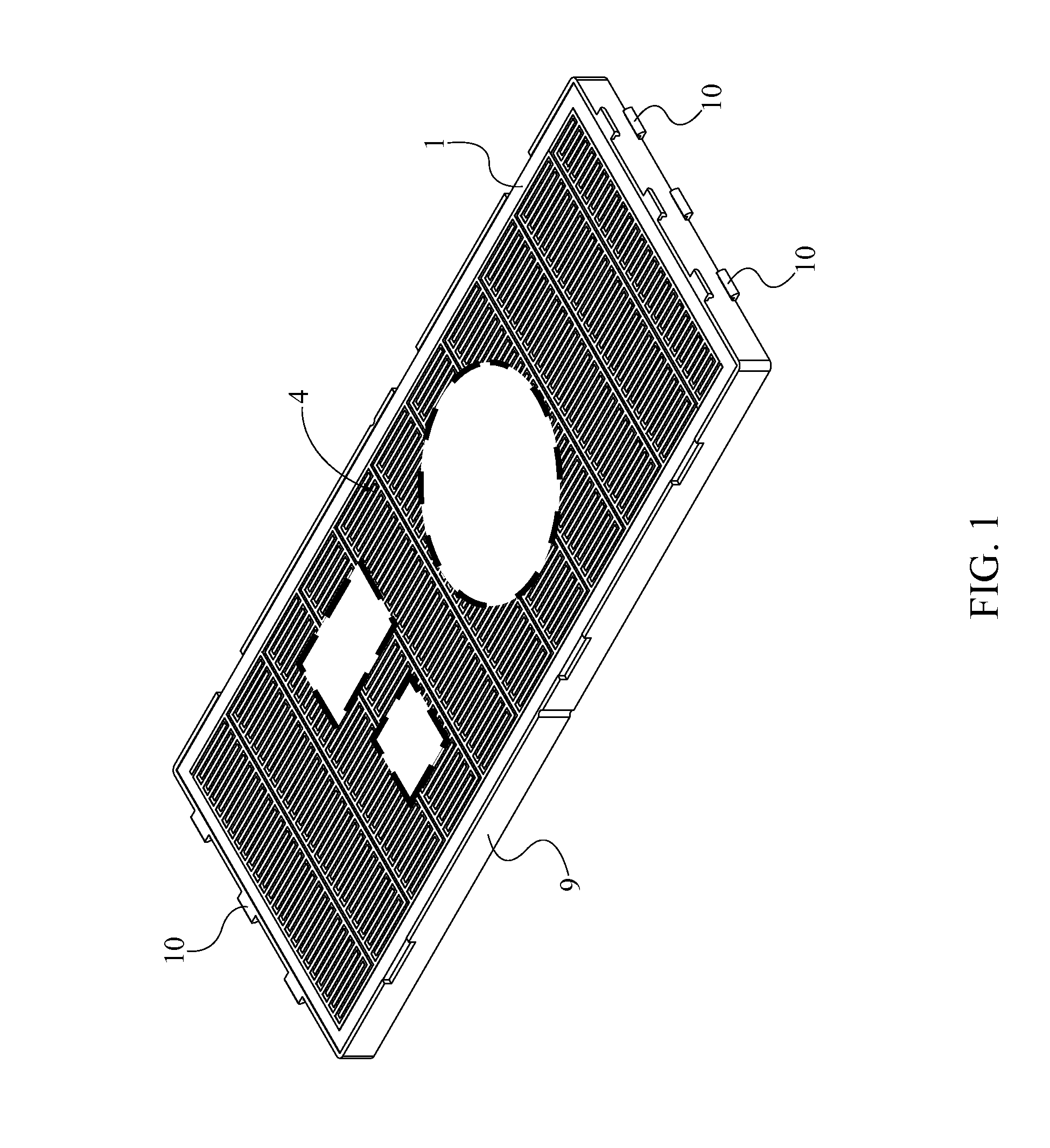
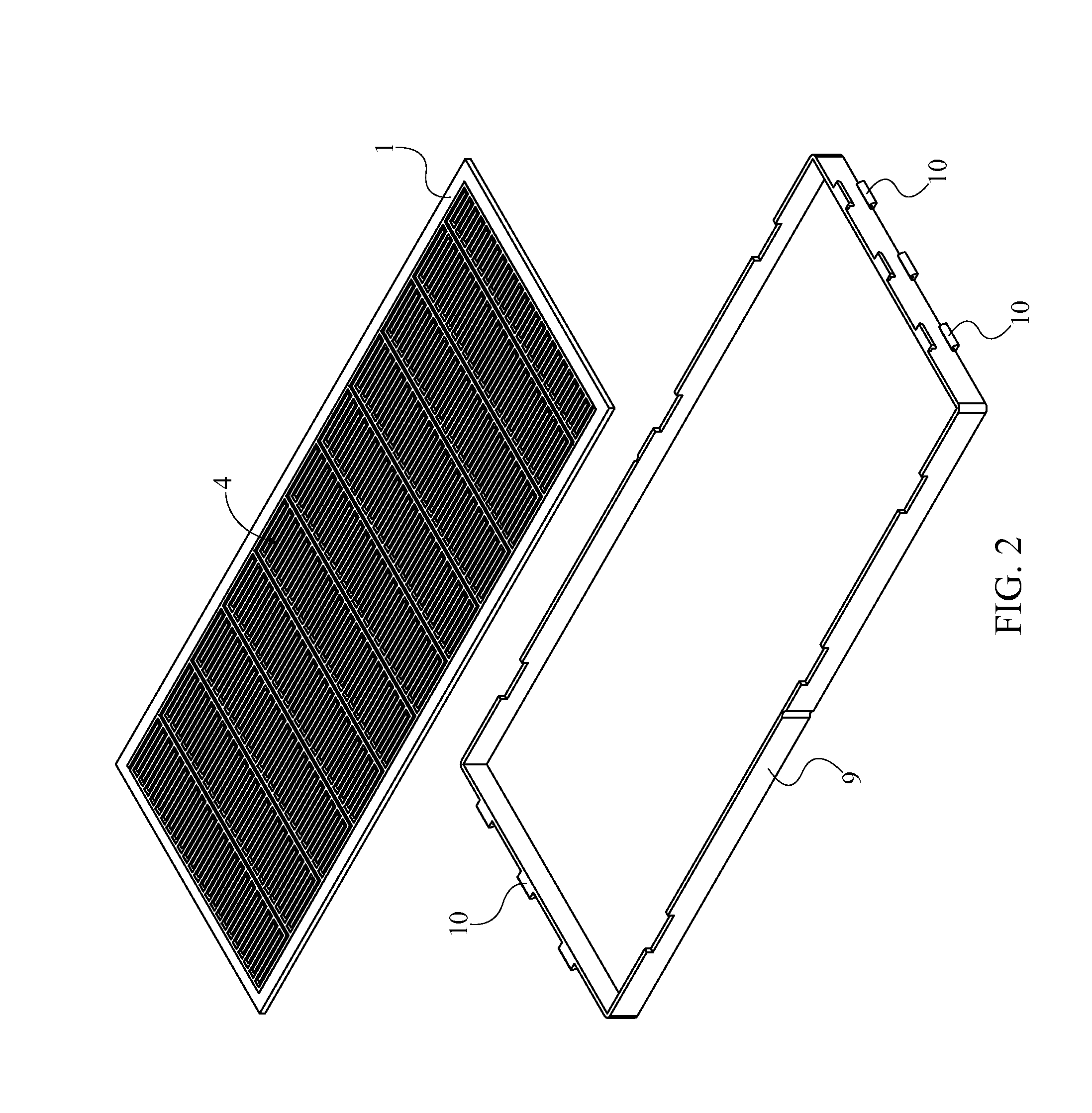
[0013]All illustrations of the drawings are for the purpose of describing selected versions of the present invention and are not intended to limit the scope of the present invention.

[0014]As can be seen in FIG. 1, the present invention is an electrostatic carrier tray, which is used to temporarily grasp and transport semiconductive wafers / coupons. A multitude of electrostatic carrier trays can be stacked on top of each other in order to increase the ease of transport or storage. The present invention can be used to bond and carry many different sizes of semiconductive wafers / coupons. The present invention mainly comprises a primary substrate 1, a plurality of electrostatic field generating (EFG) circuits 4, a conformal coating 8, a structural backing 9, and a power-delivery and control system 11, which are shown in FIGS. 2, 3, and 9. The primary substrate 1 is the base component for the present invention and is used to support the semiconductive wafers / coupons from the bottom. The p...


PUM


Abstract

An electrostatic carrier tray is an apparatus that is used to temporarily grasp and to transport semiconductive coupons/wafers. The apparatus mainly includes a primary substrate, a plurality of electrostatics field generating circuits, a conformal coating, a structural backing, and a power-delivery and control system. The electrostatics field generating circuits are positioned on one side of the primary substrate, and the power delivery and control system is positioned on the other side of the primary substrate. The electrostatics field generating circuits are used to bond the semiconductive coupons/wafers to the apparatus. The structural backing is used to handle the apparatus while transporting the semiconductive coupons/wafers and is also used to protect the power-delivery and control system from physical damage. The conformal coating is superimposed onto the electrostatics field generating circuits and the primary substrate as a means of protection.

Description

[0001]The current application claims a priority to the U.S. Provisional Patent application Ser. No. 61 / 691,508 filed on Aug. 21, 2012.FIELD OF THE INVENTION[0002]The present invention relates generally to a method and apparatus for a carrier. More specifically, the present invention is a method and apparatus for a mobile electric carrier device.BACKGROUND OF THE INVENTION[0003]With the advent of new technology, people are more reliant on electronic devices / systems in their daily routine. This causes an increase in manufacturing and producing of electronic devices and systems. Manufacturing and producing electronic devices require following stringent guidelines and strict procedures where oftentimes parts have to be transported and moved to various locations, process stations, and production plants. These parts and devices are made in many multiples of sizes and form factors, which causes manufacturers the need to maintain inventory of transport carriers (most commonly Joint Electron...

Claims


Application Information

Patent Timeline
IPC IPC(8): H02N13/00
CPCH02N13/00H01L21/6833H01L21/67333
Inventor SMITH, ERYN
Owner DIABLO CAPITAL INC
Why Eureka
Try Eureka