Rack module

Active Publication Date: 2014-02-27
MANDA ION
View PDF15 Cites 28 Cited by
  • Summary
  • Abstract
  • Description
  • Claims
  • Application Information

AI Technical Summary

Benefits of technology

[0020]The present invention permits quick access to the equipment provided within the rack unit, without needing the rack module, as secured to the rack, to

Problems solved by technology

Whilst such rail mounted equipment provides improved accessibility for inspection or maintenance, there remains a

Method used


Image

  • Rack module
  • Rack module
  • Rack module

Examples


second embodiment

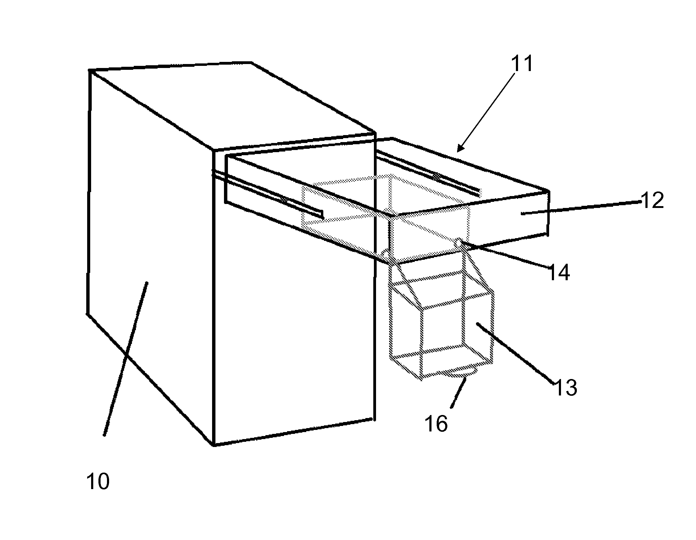
[0096]FIG. 7 shows a an exploded perspective view of the rack module, to illustrate the rack module and the rack in which it is mounted;

[0097]FIG. 8 shows a side view of the second embodiment of the rack module in a position where the tray has been slid out but not pivoted;

[0098]FIG. 9 shows a side view of the second embodiment of the rack module in a position where the tray has been slid out and pivoted into the open position;

third embodiment

[0099]FIG. 10 shows a side view of the rack module in a position where the tray has been partially slid out but not pivoted;

[0100]FIG. 11 shows a side view of the third embodiment of the rack module in a position where the tray has been slid out and pivoted into the open position;

[0101]FIG. 12 shows a rack unit which comprises a rack containing rack modules of the invention, with the trays in the closed position;

[0102]FIG. 13 shows a rack unit which comprises a rack containing rack modules of the invention, with one tray in the open position;

fourth embodiment

[0103]FIG. 14 shows a side view of the rack module in a position where the tray has been partially slid out but not pivoted;

[0104]FIG. 15 shows a side view of the fourth embodiment of the rack module in a position where the tray has been slid out and pivoted into the open position;

[0105]FIG. 16 shows a front view of the fourth embodiment of the rack module;


PUM


Abstract

A module for mounting in a rack, the module including a frame and a tray, the frame being arranged such that it may be mounted to the rack, and the tray being slidably and pivotably connected to the frame, such that the tray may be moved between a first position, in which the tray is received within the frame and lies substantially parallel to the frame, and a second position, in which the tray lies outside the frame and at an angle to the frame.

Description

[0001]The present disclosure relates to a rack module. In particular, it relates to a rack module for electronic hardware, such as computer server equipment and in particular hard disk drives.BACKGROUND TO THE INVENTION [0002]For a number of years racks have been used for mounting electronic equipment modules including, but not limited to, computer server equipment. Such racks are standardized frames or enclosures that allow for the mounting of multiple equipment modules.[0003]Commonly these racks comply to a 19-inch rack standard, wherein each module has a front panel that is 19 inches (482.6 mm) wide, including edges or ears that protrude on each side to allow the module to be fastened to the rack frame with screws. The height of the electronic modules is standardized as multiples of 1.75 inches (44.5 mm) or one rack unit (U).[0004]The use of racks with computer server equipment is particularly favourable, since it allows for dense hardware configurations without occupying excessi...

Claims


Application Information

Patent Timeline
IPC IPC(8): H05K7/14
CPCH05K7/14G11B33/128H05K7/1487H05K7/16H05K7/183G11B33/12G11B33/005G11B33/02H05K5/0256H05K7/1489
Inventor MANDA, ION
Owner MANDA ION
Why Eureka
Try Eureka