

Chain guide
- Summary
- Abstract
- Description
- Claims
- Application Information
AI Technical Summary
Benefits of technology
Problems solved by technology
Method used
Image

Examples
embodiments
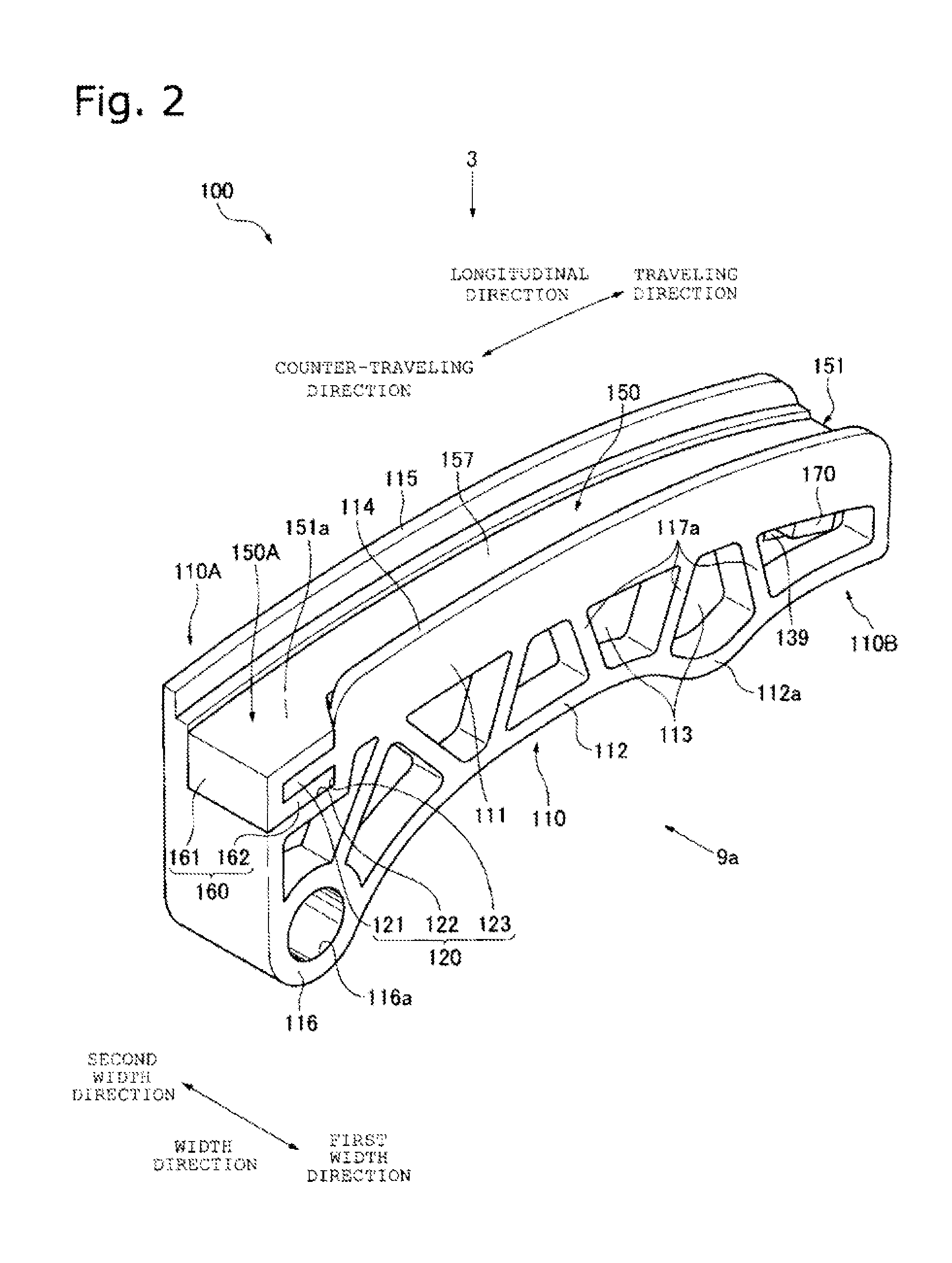
[0054]Hereinbelow, an embodiment of the present invention will be described with reference to FIGS. 1 to 15.
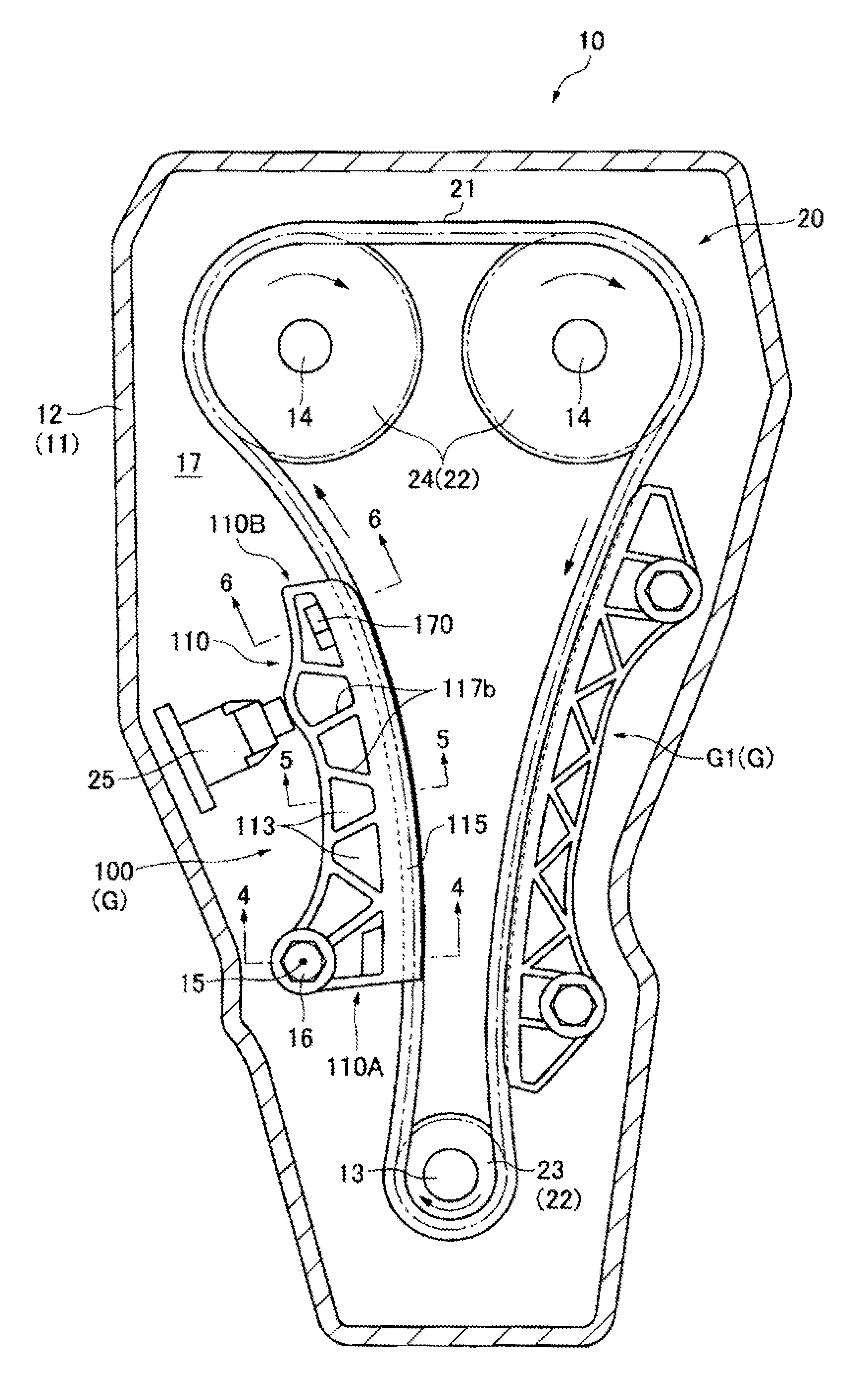
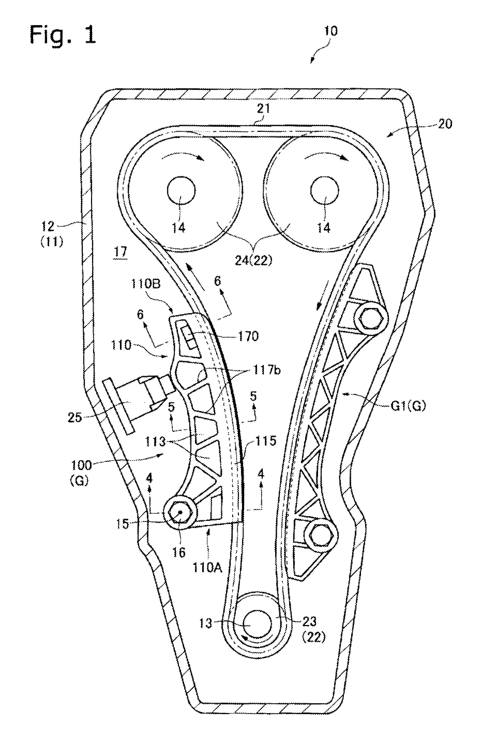
[0055]Referring to FIG. 1, in the embodiment, a movable chain guide 100 as a chain guide according to the present invention is provided in a chain drive system 20 provided in an automobile engine 10 as equipment. The drive system 20 is a timing chain drive system, and drives the valve mechanism of an internal combustion engine as the engine 10.
[0056]The drive system 20 includes an endless chain 21, a sprocket group 22 including a plurality of sprockets 23 and 24 around which the chain 21 is wound, a plurality of chain guides G that guide the traveling chain 21 driven by the sprocket group 22 and include one or more movable chain guides 100 in the present embodiment, and a tensioner 25.
[0057]In an engine main body 11 as the main body of the engine 10, the sprocket group 22 provided in an engine block 12 includes a driving sprocket 23 provided on a crankshaft 13 and a pair of dr...
PUM
 Abstract
Description
Claims
Application Information