Multiple function hydraulic system with a variable displacement pump and a hydrostatic pump-motor

a hydraulic system and variable displacement technology, applied in the field of hydraulic systems, can solve the problems of adding inefficiency to the hydraulic system, reducing the efficiency of the hydraulic system,

Inactive Publication Date: 2014-03-06
HUSCO INT INC
View PDF3 Cites 8 Cited by
  • Summary
  • Abstract
  • Description
  • Claims
  • Application Information

AI Technical Summary

Benefits of technology

[0012]One embodiment of the present hydraulic system further comprises a flow summation node that is in fluid communication with a control port for controlling displacement of the first pump. The metering orifice in each control valve varies fluid flow between the summation node and the associated hydraulic actuator. Each control valve further comprises a variable flow source orifice, and a variable bypass orifice. For example, each control valve is preferably configured so that as the metering orifice enlarges, the variable flow source orifice also enlarges and the variable bypass orifice shrinks. Inversely in that configuration, as the metering orifice shrinks, the variable flow source orifice also shrinks and the variable bypass orifice enlarges.

Problems solved by technology

Without some further compensation mechanism, this deprives the boom actuator of the necessary fluid required to operate as commanded.
Some of these mechanisms use pressure compensators and a load sensing pump, while other ones use pilot pressure signals from the operator controls to create throttling losses for the low pressure functions.
All these throttling losses generate heat and add inefficiency to the hydraulic system in order to enable the multifunction operation commanded by a machine operator.

Method used


Image

  • Multiple function hydraulic system with a variable displacement pump and a hydrostatic pump-motor
  • Multiple function hydraulic system with a variable displacement pump and a hydrostatic pump-motor
  • Multiple function hydraulic system with a variable displacement pump and a hydrostatic pump-motor

Examples


Embodiment Construction

[0019]The term “directly connected” as used herein means that the associated components are connected together by a conduit without any intervening element, such as a valve, an orifice or other device, which restricts or controls the flow of fluid beyond the inherent restriction of any conduit. If a component is described as being “directly connected” between two points or elements, that component is directly connected to each such point or element.

[0020]Although the present invention is being described in the context of use on an earth excavator, it can be implemented on other types of hydraulically operated equipment.

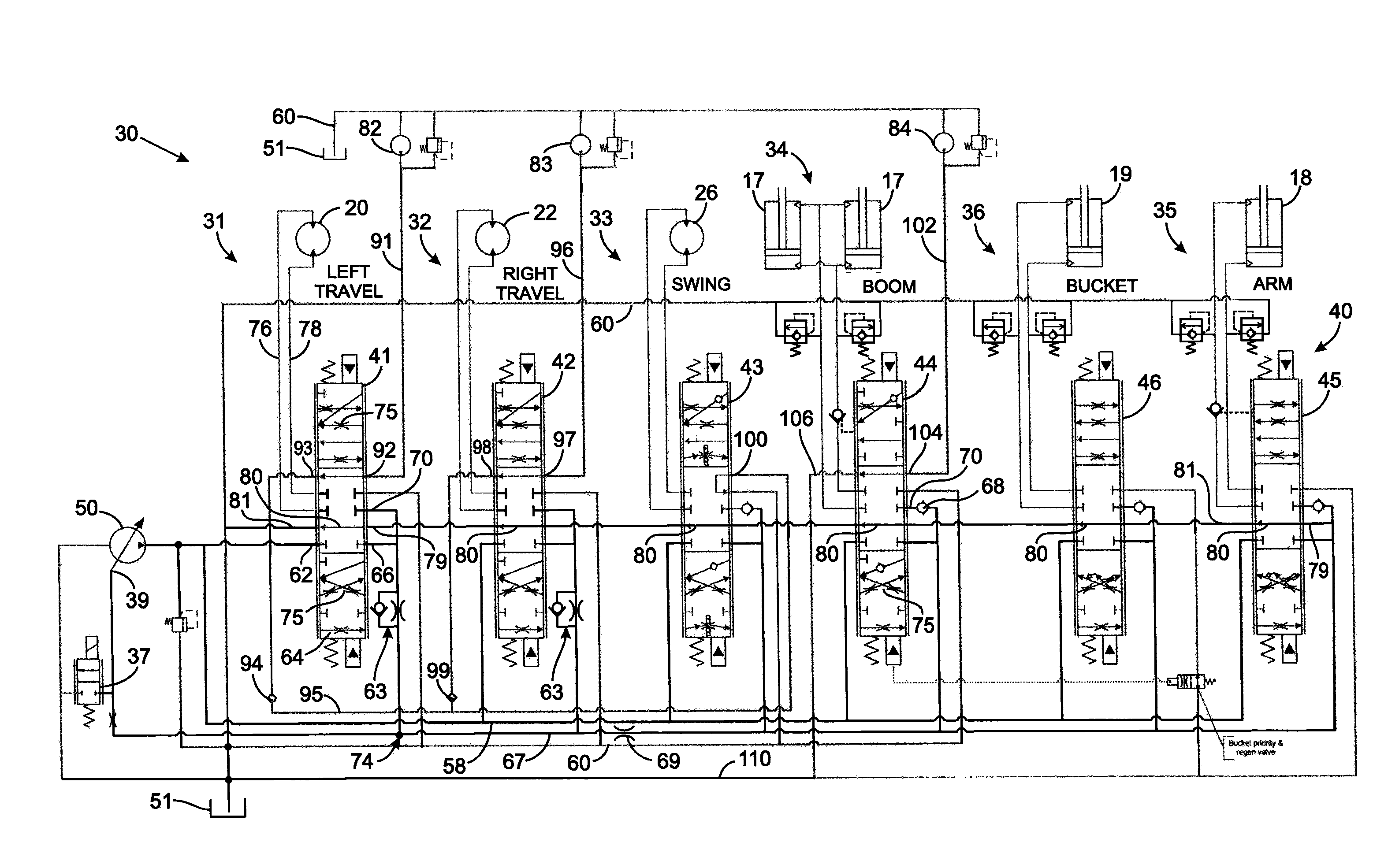
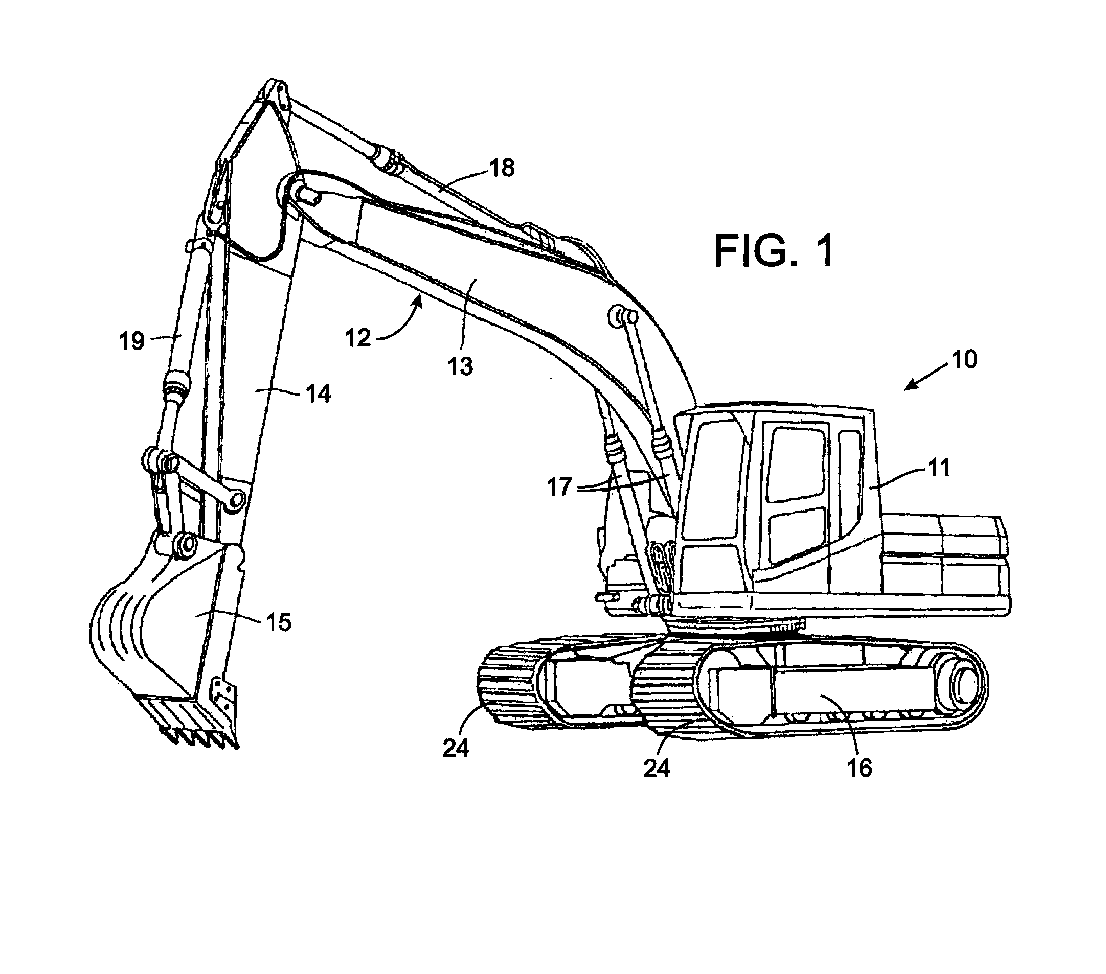
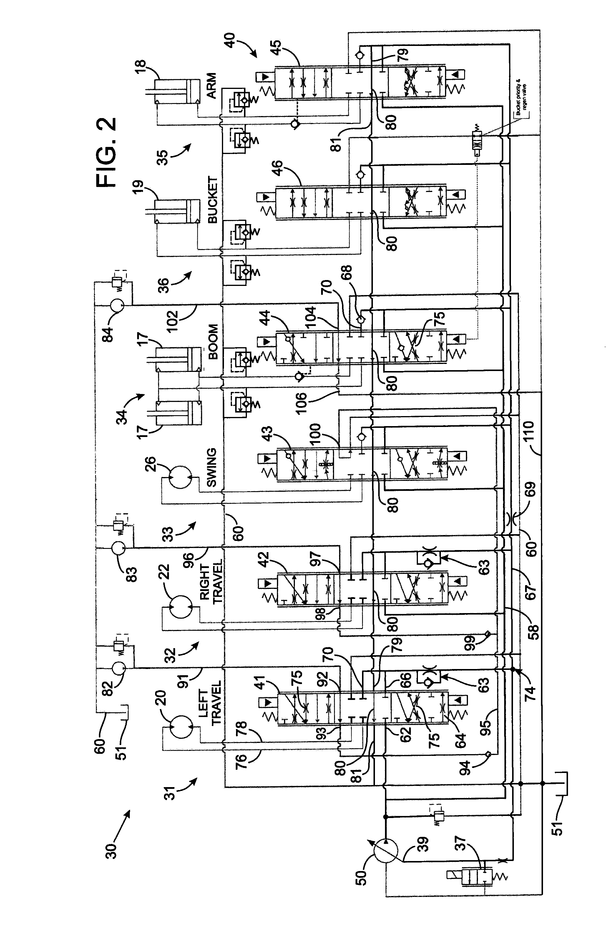
[0021]With initial reference to FIG. 1, an excavator 10 comprises a cab 11 that can swing clockwise and counter-clockwise on a crawler 16. A boom assembly 12, attached to the cab, is subdivided into a boom 13, an arm 14, and a bucket 15 pivotally attached to each other. A pair of hydraulic piston-cylinder assemblies 17, that are mechanically and hydraulically connecte...


PUM


Abstract

A hydraulic system includes a first pump and a plurality of valves that control fluid flow from the first pump to several actuators. Variable source orifices in the control valves are connected in parallel between the first pump and a node, and variable bypass orifices in the control valves are connected in series between the node and a tank. Pressure at the node controls displacement of the first pump. Each control valve also has a metering orifice for varying fluid flow between the node and one of the actuators. A hydrostatic pump-motor, coupled between two ports of a given actuator, is driven in a motoring mode by fluid exiting one of those ports. In a pumping mode, the hydrostatic pump-motor forces lower pressure fluid exhausting from one port into the other port of the given actuator.

Description

CROSS-REFERENCE TO RELATED APPLICATIONS[0001]This application claims benefit of U.S. provisional patent application no. 61 / 452,885 filed on Mar. 15, 2011.STATEMENT REGARDING FEDERALLY SPONSORED RESEARCH OR DEVELOPMENT[0002]Not ApplicableBACKGROUND OF THE INVENTION[0003]1. Field of the Invention[0004]The present invention relates to hydraulic systems having a plurality of pumps and a plurality of independently controllable hydraulic actuators; and more particularly to controlling the plurality of pumps and allocating the resultant fluid flow to the plurality of hydraulic actuators.[0005]2. Description of the Related Art[0006]Hydraulic systems have at least one hydraulic pump that supplies pressurized fluid which is feed through control valves to drive several different hydraulic actuators. A hydraulic actuator is a device, such as a cylinder-piston arrangement or a hydraulic motor that converts the flow of hydraulic fluid into mechanical motion.[0007]Because loads of different magnit...

Claims


Application Information

Patent Timeline
Patent Type & Authority Applications(United States)
IPC IPC(8): F15B7/00
CPCF15B7/003E02F9/2235E02F9/2282E02F9/2285E02F9/2292E02F9/2296F15B11/165F15B2211/20546F15B2211/253F15B2211/3116F15B2211/6052F15B2211/654F15B11/17E02F9/2242
Inventor PFAFF, JOSEPH L.HAMKINS, ERIC P.
Owner HUSCO INT INC
Why Eureka
Try Eureka