Conduction breaking device

a technology of breaking device and cutting table, which is applied in the direction of conductor severing switch, explosion-operated switch, and closing of explosion-operated switch, etc., can solve the problems of complicated adjustment process and poor execution of cutting of the cuttable portion b>81/b>a, and achieve stable cutting performance and easy adjustment

Active Publication Date: 2014-03-06
TOYODA GOSEI CO LTD
View PDF31 Cites 13 Cited by
  • Summary
  • Abstract
  • Description
  • Claims
  • Application Information

AI Technical Summary

Benefits of technology

[0007]Accordingly, it is an objective of the present invention to provide a conduction breaking device that allows the position of a cutter block to be easily adjusted to achieve stable cutting performance.

Problems solved by technology

The greater the distance, the more likely that cutting of the cuttable portion 81A will be poorly executed.
Such adjustment of positions involves a complicated process.

Method used


Image

  • Conduction breaking device
  • Conduction breaking device
  • Conduction breaking device

Examples


Embodiment Construction

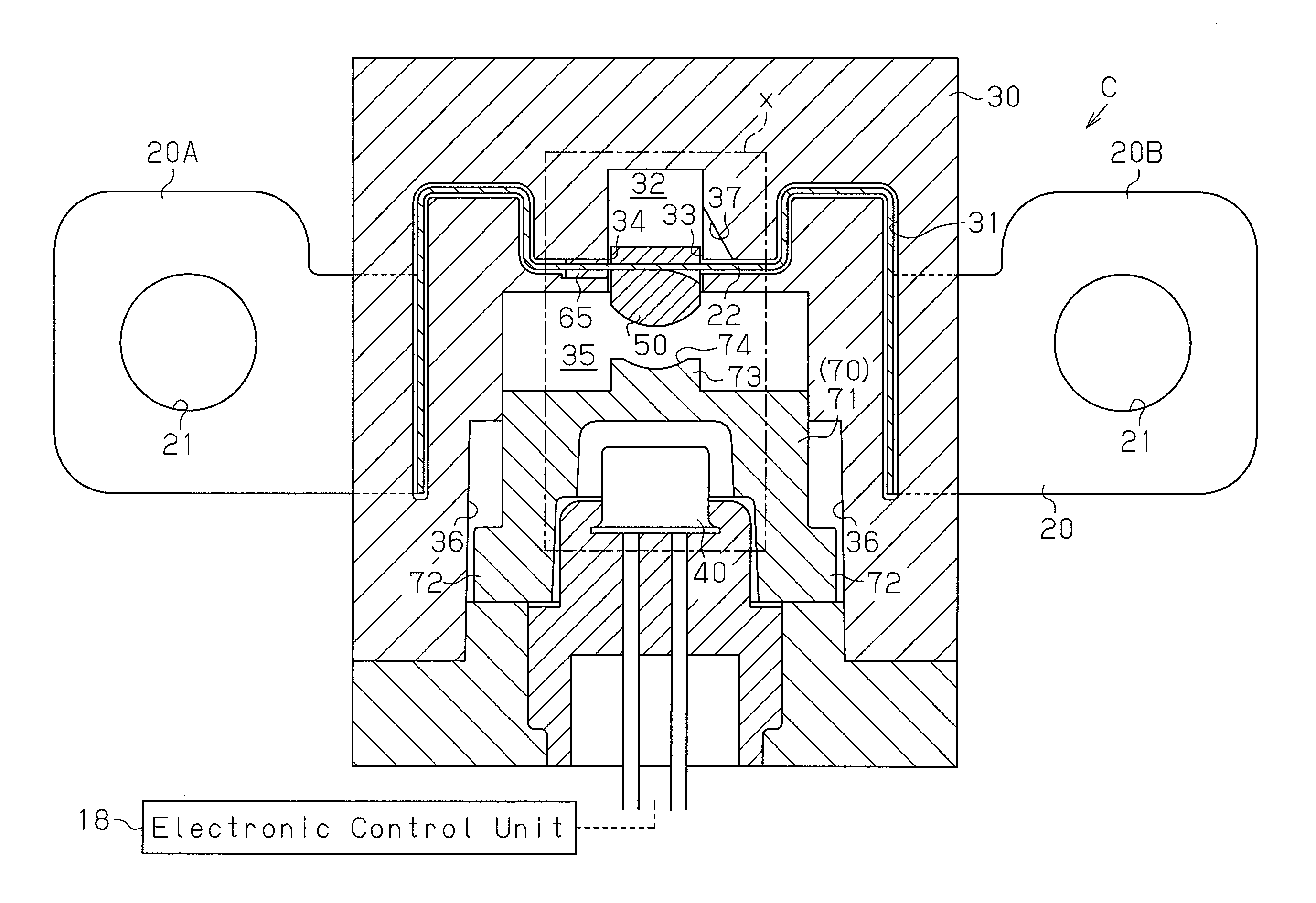
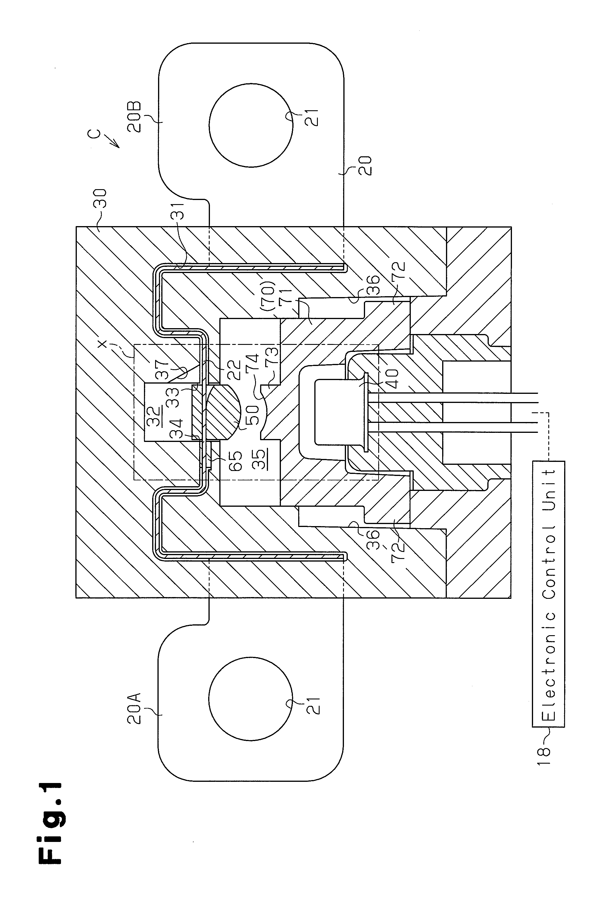
[0028]A conduction breaking device C according to one embodiment of the present invention will now be described with reference to FIGS. 1 to 6.

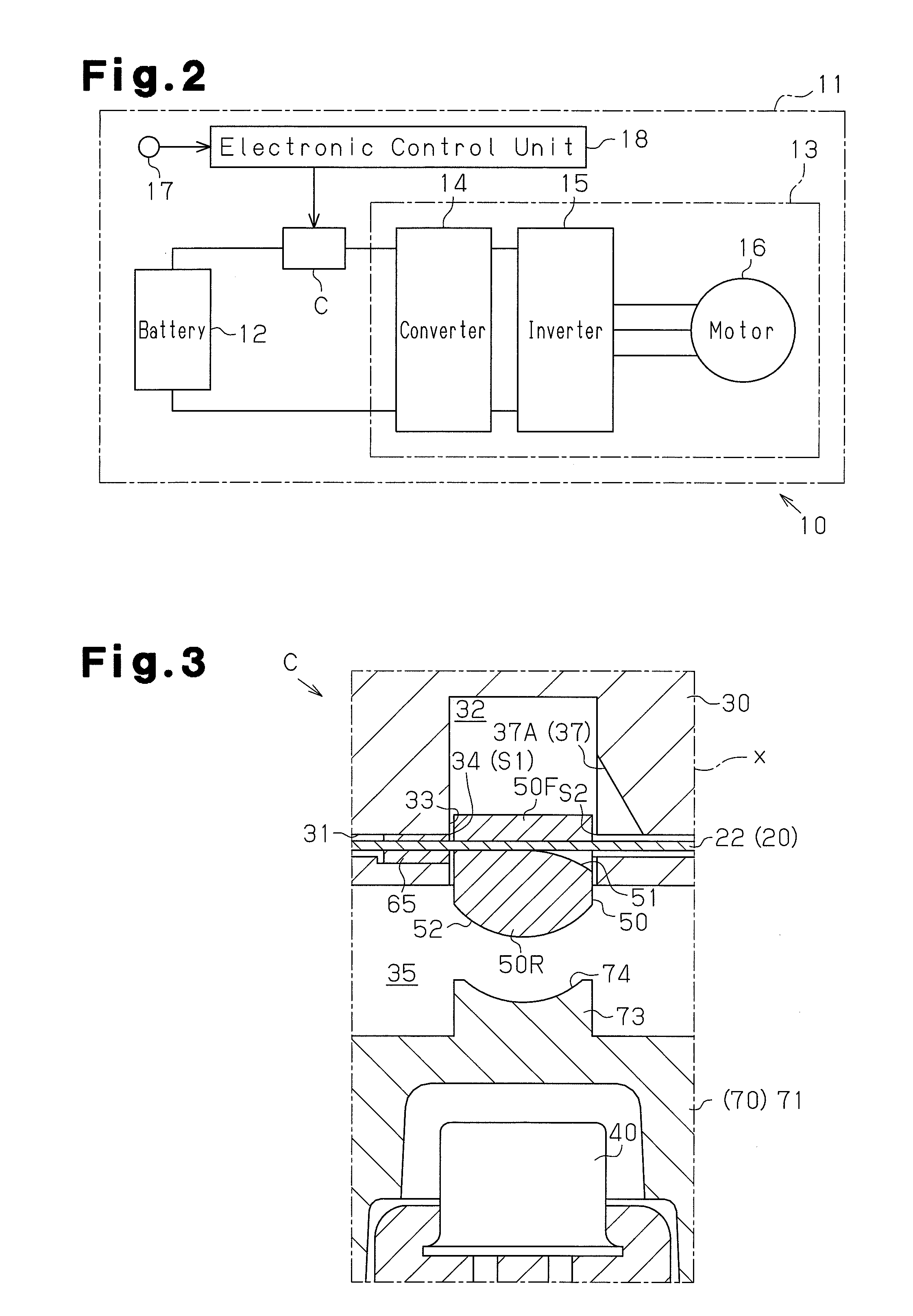
[0029]FIG. 2 shows an electric circuit 11, in which the conduction breaking device C of the present embodiment is incorporated. The electric circuit 11 includes as its components a storage battery 12 and an electric device 13. In the electric circuit 11, the electric device 13 is operated by DC electricity supplied from the storage battery 12. The electric device 13 is configured by a converter 14, which increases the voltage of electricity input from the storage battery 12 and outputs the increased voltage, an inverter 15, which converts DC electricity input from the converter 14 into AC electricity suitable for driving a motor and outputs the AC electricity, and a motor 16, which is driven by the AC electricity output from the inverter 15.

[0030]The electric circuit 11 is mounted on a vehicle 10. When the vehicle 10 is damaged, for example, ...


PUM


Abstract

A conduction breaking device is provided that uses gas from a gas generator to move a cutter block in the thickness direction of a cuttable portion, thereby cutting the cuttable portion between the moving cutter block and a cutting edge portion of a cutting chamber. The cutter block is attached to the cuttable portion such that, before generation of gas by the gas generator, a part of the cutter block is located in the cutting chamber and at a position close to the cutting edge portion in a direction along the surface of the cuttable portion.

Description

BACKGROUND OF THE INVENTION[0001]The present invention relates to a conduction breaking device for breaking conduction between a pair of devices in an electric circuit by cutting a metal conductive body extending between the devices.[0002]Electric circuits are provided with a conduction breaking device for breaking conduction between devices by being activated when malfunction occurs in a device in the electric circuit or a system on which the electric circuit is mounted. As one form thereof, a conduction breaking device has been proposed that forcibly cuts a metal conductive body located between devices by moving a blade with gas (see Japanese Patent Nos. 4228063 and 4344255, for example).[0003]This type of conduction breaking device has a basic structure as illustrated in FIG. 16. A conduction breaking device C includes a metal conductive body 81 having a cuttable portion 81A, a cutting chamber 82, a gas generator 83, and a cutter block 84. The cutting chamber 82 and the gas gener...

Claims


Application Information

Patent Timeline
Patent Type & Authority Applications(United States)
IPC IPC(8): H01H39/00
CPCH01H39/006H01H39/00H01H39/002H01H39/004H01H2039/008
Inventor NAKAMURA, YOSHIKIFUKUYAMA, TAKAKIKAMEDA, YOSHIAKI
Owner TOYODA GOSEI CO LTD
Why Eureka
Try Eureka