Unlock instant, AI-driven research and patent intelligence for your innovation.

Touch Sensing Device and Touch Point Locating Method Thereof

a technology of touch sensing and touch point, which is applied in the direction of instruments, computing, electric digital data processing, etc., can solve the problems of slow determination speed and easy interference of sensing signals

Inactive Publication Date: 2014-03-06
NOVATEK MICROELECTRONICS CORP
View PDF2 Cites 16 Cited by
  • Summary
  • Abstract
  • Description
  • Claims
  • Application Information

AI Technical Summary

Benefits of technology

The present invention provides a touch sensing device and method that can sense touch quickly and accurately. This device can generate multiple signals at the same time, which can be easily distinguished, and can quickly determine which component of the signals is causing the touch. This technology can improve the accuracy and speed of touch sensing.

Problems solved by technology

However, when the conventional touch sensing device 10 performs time-domain scanning locating, since the conventional touch sensing device 10 needs to utilize the scanning clock signals w(1)-w(k) to scan the vertical transparent electrodes Tc(1)-Tc(k) one by one and needs to capture information of the sensing signals s(1)˜s(j) in coordination with the timing synchronization signal Syn, the determining speed is slow and the sensing signals are easy to be interfered.

Method used


Image

  • Touch Sensing Device and Touch Point Locating Method Thereof
  • Touch Sensing Device and Touch Point Locating Method Thereof
  • Touch Sensing Device and Touch Point Locating Method Thereof

Examples


Embodiment Construction

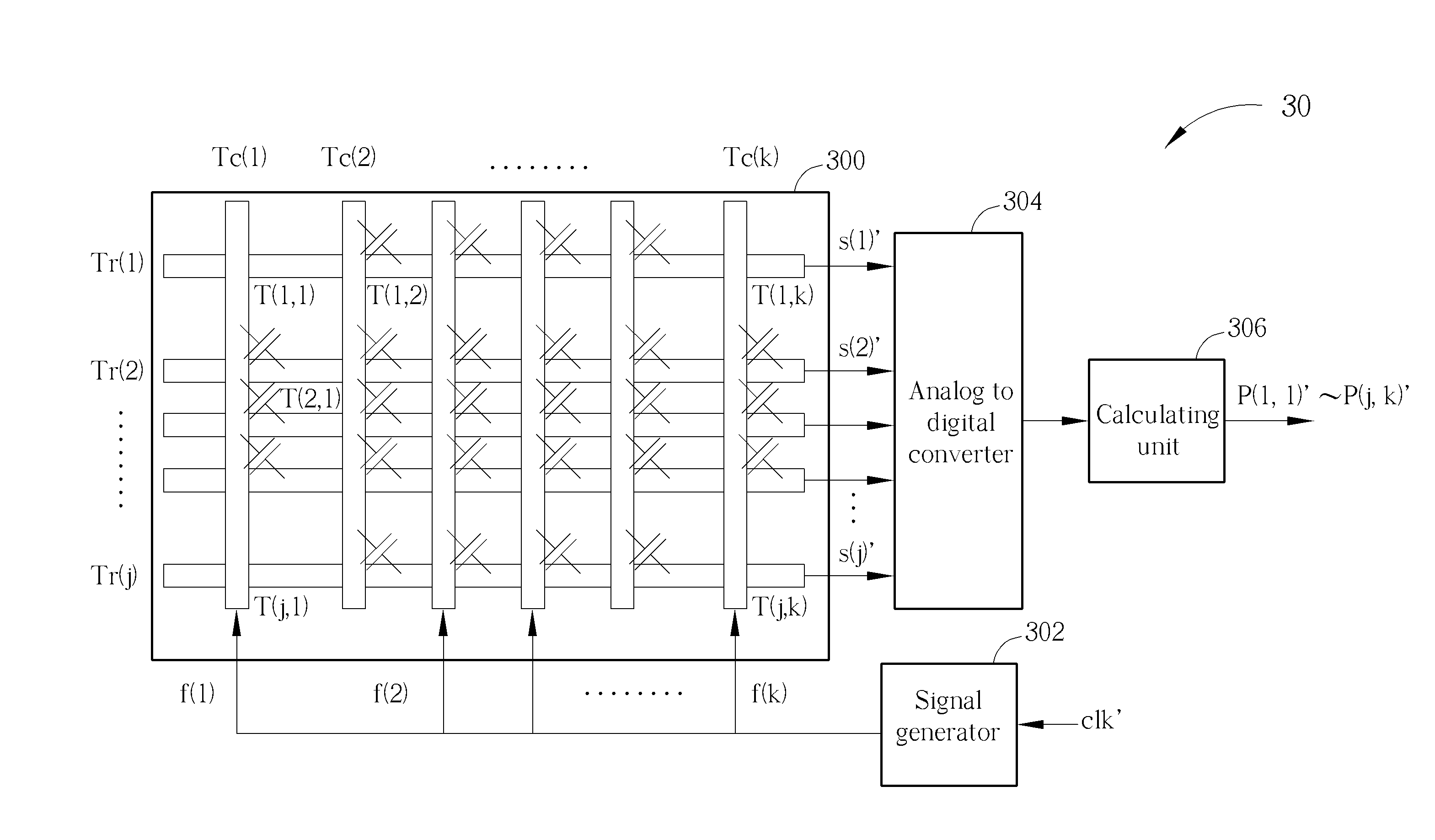
[0019]Please refer to FIG. 3, which illustrates a schematic diagram of a touch sensing device 30 according to an embodiment of the present invention. As shown in FIG. 3, the touch sensing device 30 includes a touch sensing panel 300, a signal generator 302, an analog to digital converter (ADC) 304 and a calculating unit 306. In short, since the touch sensing panel 300 and the touch sensing panel 100 are partially similar, elements and signals with the same functions are denoted by the same symbols. The touch sensing panel 300 includes vertical transparent electrodes Tc(1)-Tc(k) and horizontal transparent electrodes Tr(1)-Tr(j) to form touch sensing points T(1,1)-T(j,k). The signal generator 302 generates distinguishable signals f(1)-f(k) simultaneously coupled to the vertical transparent electrodes Tc(1)-Tc(k) according to a clock signal clk′. The analog to digital converter 304 is coupled to the horizontal transparent electrodes Tr(1)˜Tr(j) for receiving sensing signals s(1)′-s(j)′...


PUM


Abstract

A touch sensing device includes a plurality of first dimensional transparent electrodes and a plurality of second dimensional transparent electrodes, for forming a plurality of touch sensing points; one or more signal generators, for generating at least two orthogonal signals simultaneously coupled to at least two of the plurality of first dimensional transparent electrodes; one or more analog to digital converters for receiving a plurality of sensing signals from the plurality of second dimensional transparent electrodes; and one or more calculating units, for converting the plurality of sensing signals, to determine components of the at least two orthogonal signals in the plurality of sensing signals and locates at least one touch point on the plurality of touch sensing points.

Description

BACKGROUND OF THE INVENTION[0001]1. Field of the Invention[0002]The present invention relates to a touch sensing device and related touch point locating method, and more particularly, to a touch sensing device and related touch point locating method, capable of sending a plurality of distinguishable signals simultaneously for sensing, and determining each component of the plurality of distinguishable signals in sensing signals to locate touch points rapidly.[0003]2. Description of the Prior Art[0004]In general, a touch point locating method of a conventional touch sensing device utilizes time-domain scanning signals in coordination with scanning timing to capture panel sensing signals, and takes a scanning order as a corresponding arranged location for locating. For example, please refer to FIG. 1 and FIG. 2. FIG. 1 illustrates a schematic diagram of a conventional touch sensing device 10. FIG. 2 illustrates a schematic diagram of scanning clock signals w(1)-w(k) and a timing synchr...

Claims


Application Information

Patent Timeline
Patent Type & Authority Applications(United States)
IPC IPC(8): G06F3/041
CPCG06F3/041G06F3/04166G06F3/0446
Inventor TANG, WING-KAI
Owner NOVATEK MICROELECTRONICS CORP