
Touch sensing method, processor and system

Active Publication Date: 2014-03-06
EGALAX EMPIA TECH INC
View PDF3 Cites 17 Cited by
  • Summary
  • Abstract
  • Description
  • Claims
  • Application Information

AI Technical Summary

Benefits of technology

The present invention relates to a method, processor, and system for improving touch sensing by reducing noises caused by electronic components and environmental variations. The technical effect of the invention is to provide more accurate and reliable data for touch sensing.

Problems solved by technology

In other words, performing detections a number of times on the plurality of sensors is needed to generate the 2D sensing information, which will take a consider amount of time.
However, a large proportion of the 2D sensing information is irrelevant to touches, so continuously performing detections irrelevant to touches is time and power consuming.
Thus, how to save time and power is a technically critical.
In order to solve these problems, efforts have long been made in vain, while ordinary products and methods offering no appropriate structures and methods.

Method used


Image

  • Touch sensing method, processor and system
  • Touch sensing method, processor and system
  • Touch sensing method, processor and system

Examples


first embodiment

[0137]In the present invention, a method for capacitive position detection is provided as shown in FIG. 6A. First, in step 610, a capacitive sensing device with a plurality of sensors is provided, wherein these sensors include a plurality of first sensors and a plurality of second sensors, and these first and second sensors intersect at a plurality of intersections. Next, in step 620, each touch-related sensor is detected. Next, in step 630, at least a mutual capacitive detection range is determined based on all of the touch-related sensors. Then, in step 640, mutual capacitive detection is carried out on the at least one mutual capacitive detection range to determine sensing information of the at least one mutual capacitive detection range. Then, in step 650, a 2D sensing information is generated based on the sensing information of the at least one mutual capacitive detection range.

[0138]In step 620, the touch-related sensors can be determined by self-capacitive detection. For exam...

second embodiment

[0152]In the present invention, a method for capacitive position detection is provided as shown in FIG. 7A. First, in step 710, a 2D sensing information is obtained. Next, in step 720, at least a 1D sensing information is obtained. Then, in step 730, when the capacitive sensing device is touched or approached, at least a detected range in the 2D sensing information is determined based on the at least 1D sensing information. Thereafter, in step 740, each touch-related sensing information is determined in the at least one detected range.

[0153]The plurality of 1D sensing information above can be obtained by a capacitive sensing device. The capacitive sensing device includes a plurality of sensors. These sensors include a plurality of first sensors and a plurality of second sensors, wherein the first and second sensors intersect at a plurality of intersections. Moreover, steps 710 and 720 above can be performed by the controller 160. In addition, steps 730 and 740 above can be performed...

third embodiment

[0167]In the present invention, an image of signal values is segmented into line pieces based on a predefined condition. This predefined condition may specify a line piece as a plurality of continuous non-zero values, or one or a plurality of continuous values exceeding a threshold.

[0168]In a second embodiment of the present invention, a predefined condition is used for segmenting an image of differences into line pieces. The predefined condition may specify a line piece as a group of continuous positive values with an adjacent group of continuous negative values, wherein there is no zero values between the continuous positive values and the continuous negative values, or there can be at least one zero value. Furthermore, the predefined condition may specify a line piece as beginning with a value greater than a positive threshold and ending with a value smaller than a negative threshold.

[0169]In an example of the present invention, differences are indicated by continuous positive va...


PUM


Abstract

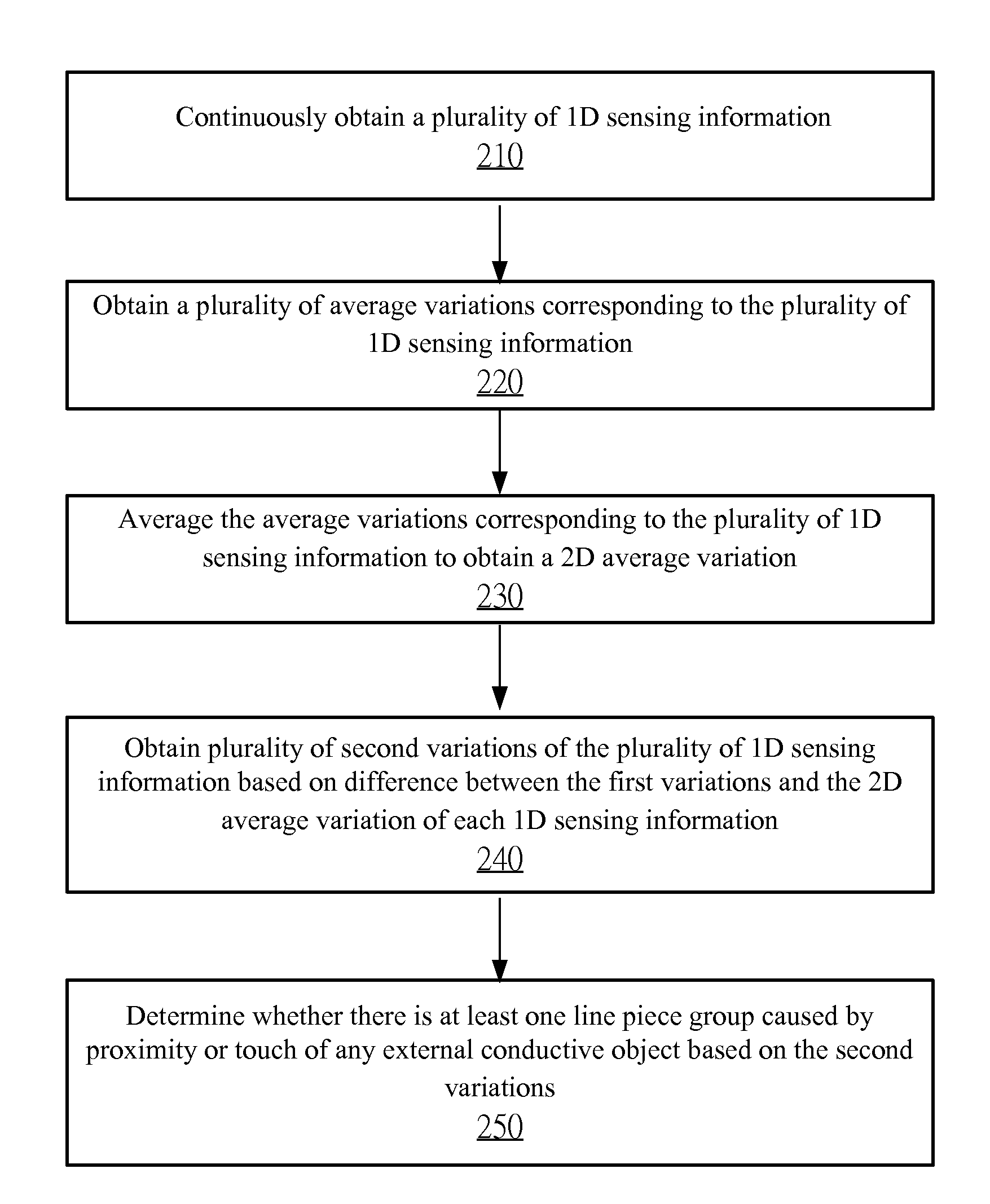
The invention provides a touch sensing method. The touch sensing method comprises the following steps: obtaining a first 1-D sensing information, wherein the first 1-D sensing information comprises a plurality of first values; obtaining a second 1-D sensing information, wherein the second 1-D sensing information comprises a plurality of second values, wherein the positions of the first values respectively correspond to the positions of the second values, and the first 1-D sensing information is generated when no external conductive object approaches or touches; determining a plurality of first variations based on the differences between the first values and the corresponding second values; determining an average variation based on all or part of the first variations; and determining a plurality of second variations based on the differences between the first variations and the average variation.

Description

CROSS REFERENCE TO RELATED APPLICATIONS[0001]This application claims the benefit of U.S. Provisional Application No. 61 / 695,805, filed on Aug. 31, 2012, which is herein incorporated by reference for all intents and purposes.BACKGROUND OF THE INVENTION[0002]1. Field of the Invention[0003]The present invention relates to a touch sensing method, processor and system for avoiding the noises from the environmental variation.[0004]2. Description of the Prior Art[0005]Touch displays are widely used in may electronic devices. One approach is to define a two dimensional (2D) touch area on a touch display with the use of a touch sensing panel, so as to obtain sensing information through scanning of horizontal and vertical axes on the touch panel in order to determine the touch or proximity of an external object such as a finger on the touch panel. A capacitive touch display is provided by U.S. Pat. No. 4,639,720, for example.[0006]Sensing information can be converted into a plurality of conti...

Claims


Application Information

Patent Timeline
IPC IPC(8): G06F3/044
CPCG06F3/044G06F3/0416G06F3/045G06F3/04162G06F3/04166G06F3/0441G06F3/0442G06F3/0445G06F3/0446
Inventor CHANG, CHIN-FUYEH, SHANG-TAI
Owner EGALAX EMPIA TECH INC
Learn More