Pumping cap for applying suction to printhead

Inactive Publication Date: 2014-03-06
MIDWEST ATHLETICS & SPORTS ALLIANCE LLC
View PDF2 Cites 6 Cited by
  • Summary
  • Abstract
  • Description
  • Claims
  • Application Information

AI Technical Summary

Benefits of technology

The invention is an inkjet printer that has a printhead with nozzles and a cap with a base and a sealing face. The printer uses suction to prime the nozzles when the base is moved from a first position to a second position. A valve is also included to relieve excess pressure in the cap. The technical effect of this invention is to improve the performance and reliability of inkjet printers.

Problems solved by technology

Such air bubbles can cause ejected drops to be misdirected from their intended flight paths, or to have a smaller drop volume than intended, or to fail to eject.
A dedicated motor results in additional cost and takes up additional space in the printer.
Such a gear train can cause additional noise during operation, and requires additional drive power from the motor in order to turn the gears.
In addition, it can take ten seconds or more to generate sufficient suction to prime a printhead using a tube pump.
Such a removal mechanism for accumulated ink adds undesirable complexity to the priming system.

Method used


Image

  • Pumping cap for applying suction to printhead
  • Pumping cap for applying suction to printhead
  • Pumping cap for applying suction to printhead

Examples


first embodiment

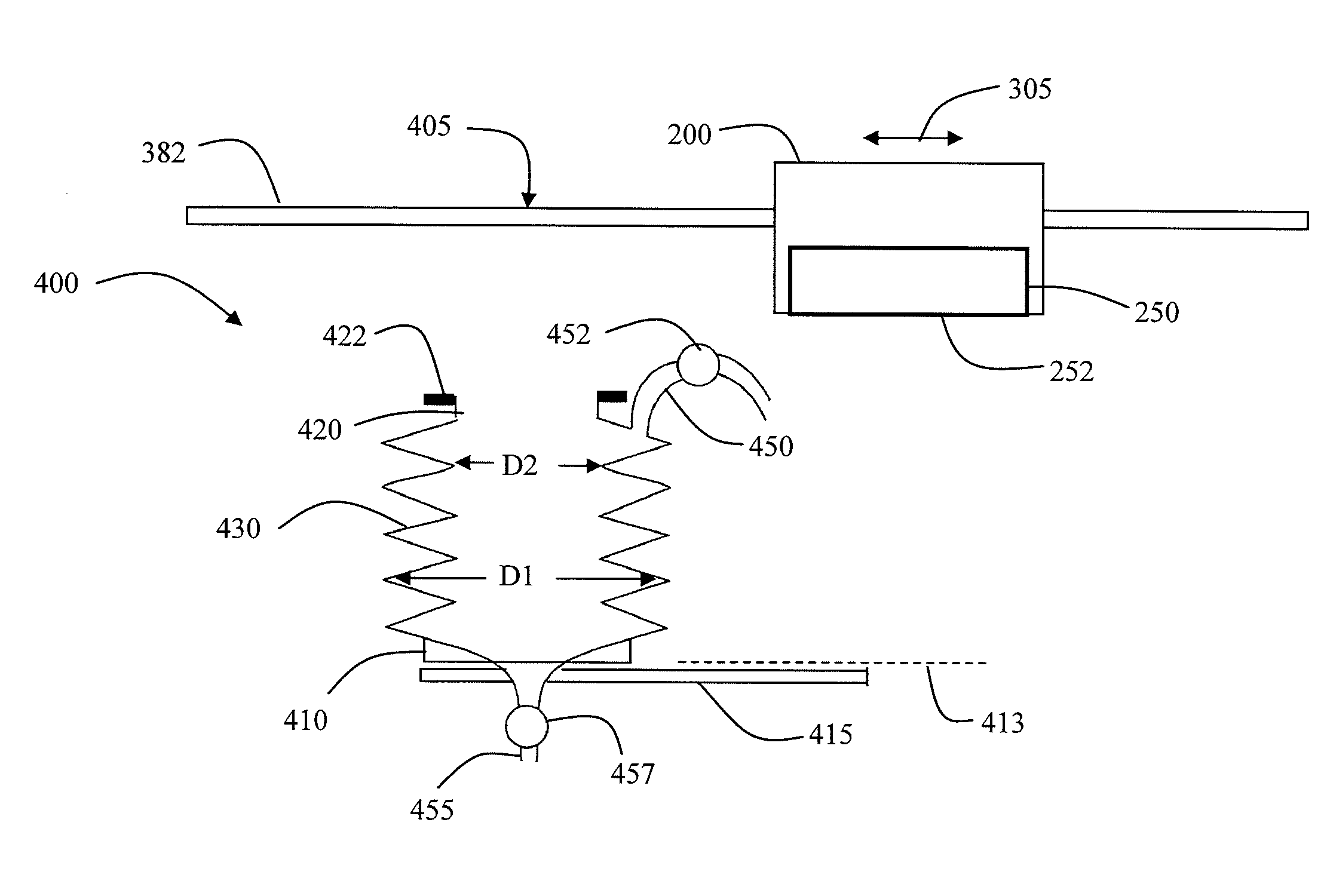
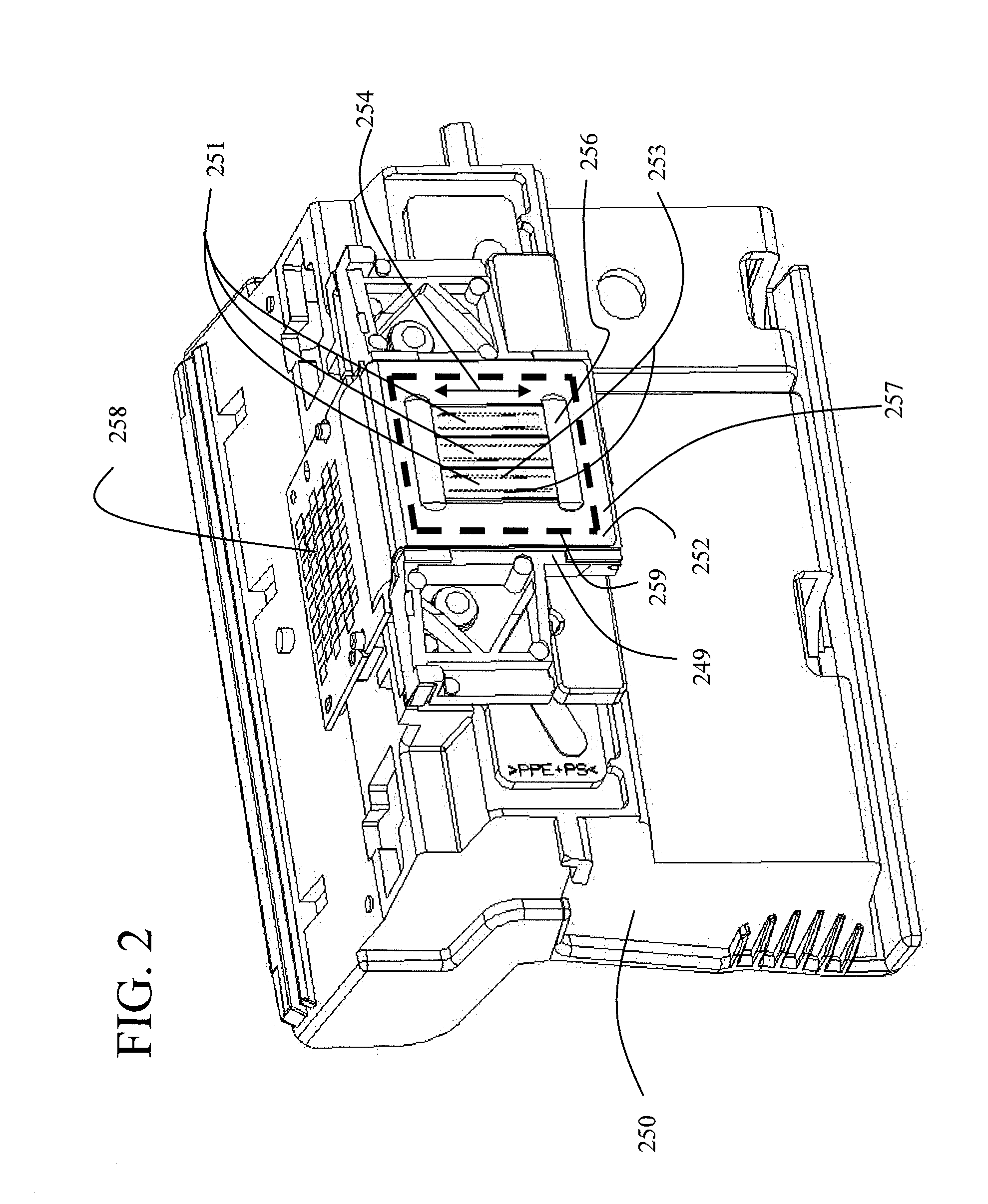
[0041]As the cap base elevator 415 moves the cap base 410 away from the first position 411 to the second position 412, it can be advantageous to physically hold the sealing face 422 of the pumping cap 400 against the printhead face 252 so that suction is generated in the pumping cap 400, rather than simply pulling the sealing face 422 away from the printhead face 252. FIG. 9 shows a holding mechanism in which a permanent magnet 425 is mounted below the frame 420 near the sealing face 422. In this embodiment, an electromagnet is mounted on the printhead 250 below the flex circuit 257 in a position corresponding to the capping region 259. When the electromagnet is turned on, the permanent magnet 425 is attracted toward the printhead face 252, thereby holding the sealing face 422 against the printhead face 252. The electromagnet is turned off when it is desired to move the sealing face 422 away from the printhead face 252.

second embodiment

[0042]A second type of holding mechanism is shown in the side views of FIGS. 10 and 11. In this second embodiment, a lever arm 460 is pivotably attached to the cap base 410 by a first pin 461. The lever arm 460 includes a slot 464 through which a second pin 462 extends, thereby slidingly attaching the lever arm 460 to the frame 420. Optionally, the end of the lever arm 460 near the frame 420 is shaped like a two pronged fork, so that another pin (not shown) on the opposite side of the frame 420 also slidingly attaches the lever arm 460 to the frame 420. Motion of the lever arm 460 controls the distance between the cap base 410 and the frame 420. In FIG. 10, the cap base 410 is at its first position 411 and the compressible portion 430 is compressed. In FIG. 11, the cap base 410 is at its second position 412 so that the compressible portion 430 is not compressed. The vent valve 452 and the drain valve 457 are shown in their closed positions in FIG. 10 so that a suction pressure is ge...


PUM


Abstract

An inkjet printer includes an inkjet printhead including nozzles disposed in a printhead face; a cap including: a base; and a sealing face for sealing around the printhead face, wherein suction is generated at the printhead face for priming the nozzles when the base is moved from a first position to a second position, wherein the first position is located a smaller distance from the sealing face than the second position; and a valve having an open position and a closed position, wherein the valve is configured to be in the open position when the base of the cap is moved from the second position to the first position for relieving excess pressure in the cap.

Description

CROSS REFERENCE TO RELATED APPLICATIONS[0001]Reference is made to commonly assigned, co-pending U.S. patent application Ser. No. ______ (K001246), concurrently filed herewith, entitled “Method of Maintaining an Inkjet Printhead” by Randolph Dumas et al, the disclosure of which is herein incorporated by reference.FIELD OF THE INVENTION[0002]This invention relates generally to the field of printhead maintenance in an inkjet printer, and more particularly to configurations of a cap for applying suction to the nozzles of an inkjet printhead.BACKGROUND OF THE INVENTION[0003]An inkjet printing system typically includes one or more printheads and their corresponding ink supplies. A printhead includes an ink inlet that is connected to its ink supply and an array of drop ejectors, each ejector including an ink pressurization chamber, an ejecting actuator and a nozzle through which droplets of ink are ejected. The ejecting actuator may be one of various types, including a heater that vaporize...

Claims


Application Information

Patent Timeline
IPC IPC(8): B41J2/165
CPCB41J2/16511B41J2/16532
Inventor DUMAS, RANDOLPH E.KNEEZEL, GARY ALAN
Owner MIDWEST ATHLETICS & SPORTS ALLIANCE LLC
Why Eureka
Try Eureka