Tension control in a web transport system

a web transport system and tension control technology, applied in the direction of thin material processing, printing presses, printing, etc., can solve the problems of unacceptable variation of the registration direction of the plurality of printheads along the media travel path, and achieve the effect of reducing the amount of stretch in the print media, better registration of the plurality, and better control of adjusting the tension

Inactive Publication Date: 2014-03-06
EASTMAN KODAK CO
View PDF5 Cites 4 Cited by
  • Summary
  • Abstract
  • Description
  • Claims
  • Application Information

AI Technical Summary

Benefits of technology

[0006]An advantage of the present invention is that it provides better control over adjusting the tension in the print media in the tension zone, thus reducing the amount of stretch in the print media. This allows for better registration of the plurality of printheads in the printing system, resulting in a higher quality print.
is that it provides better control over adjusting the tension in the print media in the tension zone, thus reducing the amount of stretch in the print media. This allows for better registration of the plurality of printheads in the printing system, resulting in a higher quality print.

Problems solved by technology

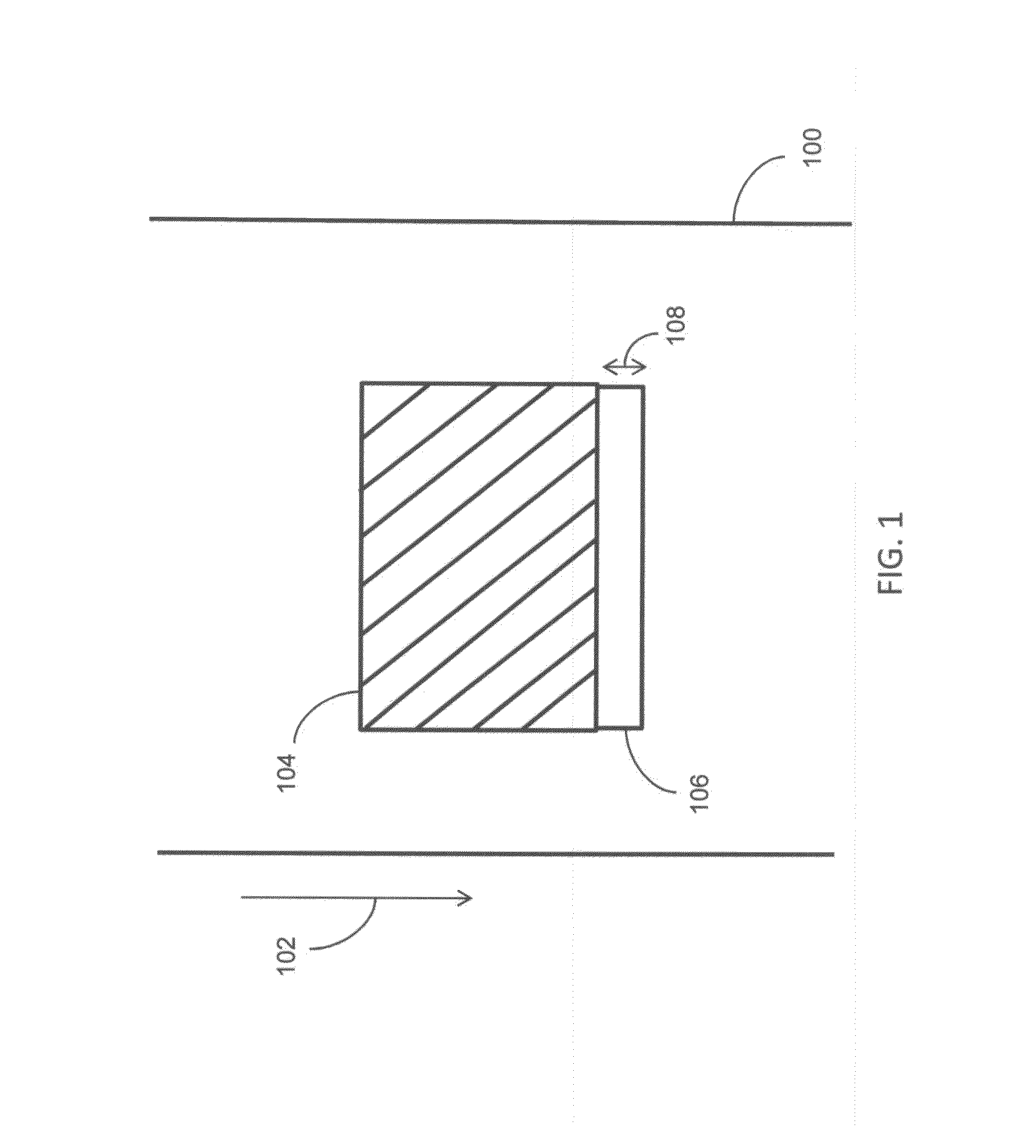
It has been found that in some printing applications, depending, for example, on ink coverage levels and the ink and print media types, that the registration of the plurality of printheads along the direction of the media travel can vary unacceptably when using a PID control algorithm to maintain the tension of the print media as it is moved through the printing system.

Method used


Image

  • Tension control in a web transport system
  • Tension control in a web transport system
  • Tension control in a web transport system

Examples


Embodiment Construction

[0012]The following terms take the meanings explicitly associated herein, unless the context clearly dictates otherwise. The meaning of “a,”“an,” and “the” includes plural reference, the meaning of “in” includes “in” and “on.”Additionally, directional terms such as “on”, “over”, “top”, “bottom”, “left”, “right” are used with reference to the orientation of the Figure(s) being described. Because components of embodiments of the present invention can be positioned in a number of different orientations, the directional terminology is used for purposes of illustration only and is in no way limiting.

[0013]The present description will be directed in particular to elements forming part of, or cooperating more directly with, an apparatus in accordance with the present invention. It is to be understood that elements not specifically shown, labeled, or described can take various forms well known to those skilled in the art. It is to be understood that elements and components can be referred t...


PUM

PropertyMeasurementUnit
tensionaaaaaaaaaa
speedaaaaaaaaaa
colorsaaaaaaaaaa

Abstract

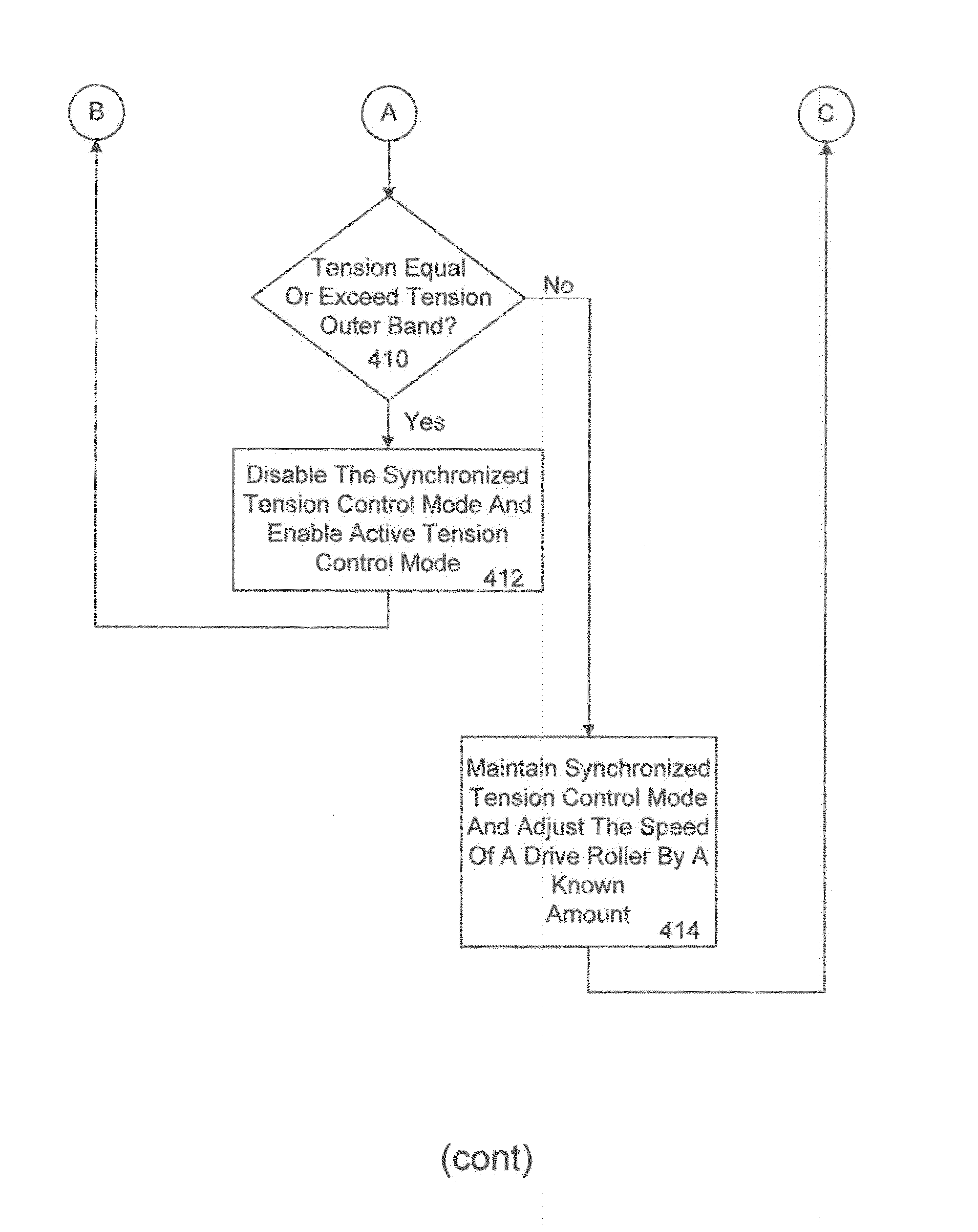
A method for controlling tension in a print media in a tension zone of a printing system comprises enabling an active tension control mode until the tension in the print media is in a stable state for a given period of time. Then, the active tension control mode is disabled and a synchronized control mode is enabled. The tension in the print media is monitored to determine if the tension exceeds a tension inner band but does not exceed a tension outer band while the synchronized control mode is enabled. The speed of a drive roller is adjusted in response to this determination. The tension in the print media is also monitored to determine if the tension exceeds the tension outer band while the synchronized control mode is enabled. The synchronized control mode is disabled in response to this determination and the active tension control mode is enabled.

Description

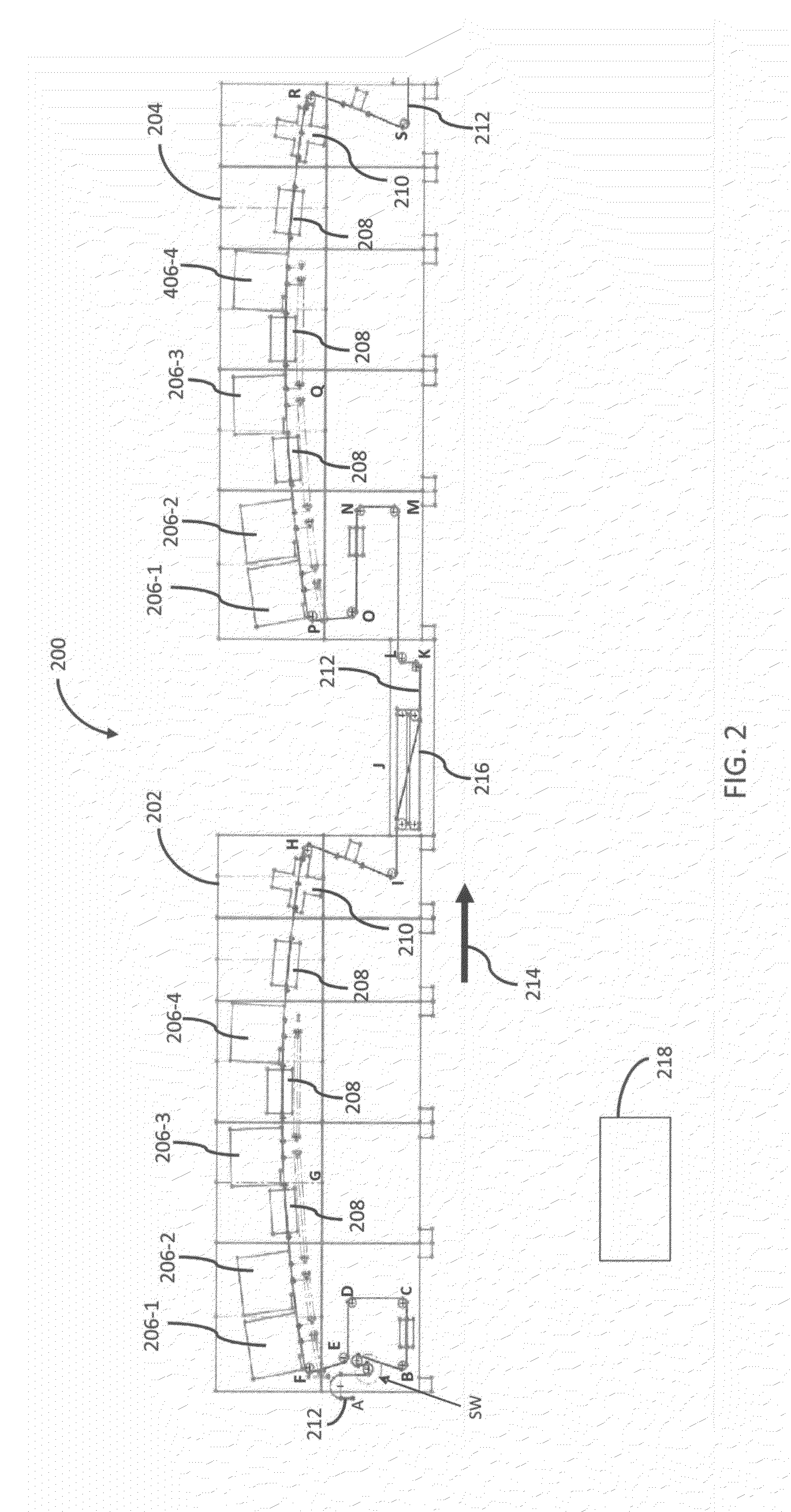
CROSS REFERENCE TO RELATED APPLICATIONS[0001]This application claims the benefit of U.S. Provisional Application No. 61 / 696,848 filed Sep. 5, 2012.[0002]Reference is made to commonly-assigned, U.S. application Ser. No. ______ (Docket K001475), entitled “METHOD FOR CONTROLLING TENSION IN A WEB”, filed concurrently herewith.FIELD OF THE INVENTION[0003]The present invention generally relates to web transport systems used in printing systems and more particularly to controlling tension in a continuous web in a web transport system.BACKGROUND OF THE INVENTION[0004]In high speed inkjet printers, a media transport is used to move a web of print media past a plurality of printheads. The printheads are positioned sequentially along the media path to print each of the plurality of ink colors. The web of print media is kept under tension as it is moved along the media path. Prior art systems, such as the Kodak Versamark 100 series printers have used a proportional integrate derivative (PID) co...

Claims


Application Information

Patent Timeline
Patent Type & Authority Applications(United States)
IPC IPC(8): B41J13/00
CPCB41J13/0009B41F13/02B41F13/03B41J15/165B65H23/1888B65H2220/02B65H2301/332B65H2513/11B65H2515/31B65H2220/01B65H2220/03
Inventor NIERTIT, THOMASARMBRUSTER, RANDY E.SCHROEDER, LOTHAR J.MACKENZIE, SCOTT P.
Owner EASTMAN KODAK CO
Why Eureka
Try Eureka