Systems and Methods for Monitoring a Subsea Environment

a monitoring system and subsea environment technology, applied in the field of optical analysis systems, can solve problems such as the possibility of a leakage in most of the components of the subsea well system, the complexity of the system and the number of individual components in the deepwater system, and the severe test of the subsea wellbore equipment and control system

Inactive Publication Date: 2014-03-06
HALLIBURTON ENERGY SERVICES INC
View PDF9 Cites 21 Cited by
  • Summary
  • Abstract
  • Description
  • Claims
  • Application Information

AI Technical Summary

Benefits of technology

[0006]In some aspects of the disclosure, a system is disclosed that includes one or more subsea equipment arranged in an oceanic environment, and at least one optical computing device arranged on or in proximity to the one or more subsea equipment for monitoring the oceanic environment, the at least one optical computing device having at least one integrated computational element configured to optically interact with the oceanic environment and thereby generate optically interacted light, and at least one detector arranged to receive the optically interacted light and generate an output signal corresponding to a characteristic of the oceanic environment.
[0007]In other aspects of the disclosure, a method of monitoring a fluid disclosed. The method may include arranging at least one optical computing device within an oceanic environment that includes one or more subsea equipment, the at least one optical computing device having at least one integrated computational element and at least one detector arranged therein, disposing the at least one optical computing device...

Problems solved by technology

As the oil and gas industry moves into deeper waters across the globe, the capabilities of subsea wellbore equipment and control systems are severely tested.
In spite of significant advances in engineering, the complexity of the systems and the number of individual components in deepwater systems create numerous potential leak sites.
Over the life of a subsea system, it is possible for a leak to occur in most of the components of a subsea well system.
For example, connection leaks are often found in umbilical lines, hydraulic lines, control systems, flow hubs, casing, and similar components.
Dynamic seal leaks are often experienced in surface-controlled subsurface safety valves (SCSSV), actuators, valves control systems and similar components.
Static seal leaks are often seen in wellheads, packers, hangers, subsea separation and compression systems, and similar compon...

Method used


Image

  • Systems and Methods for Monitoring a Subsea Environment
  • Systems and Methods for Monitoring a Subsea Environment
  • Systems and Methods for Monitoring a Subsea Environment

Examples


Embodiment Construction

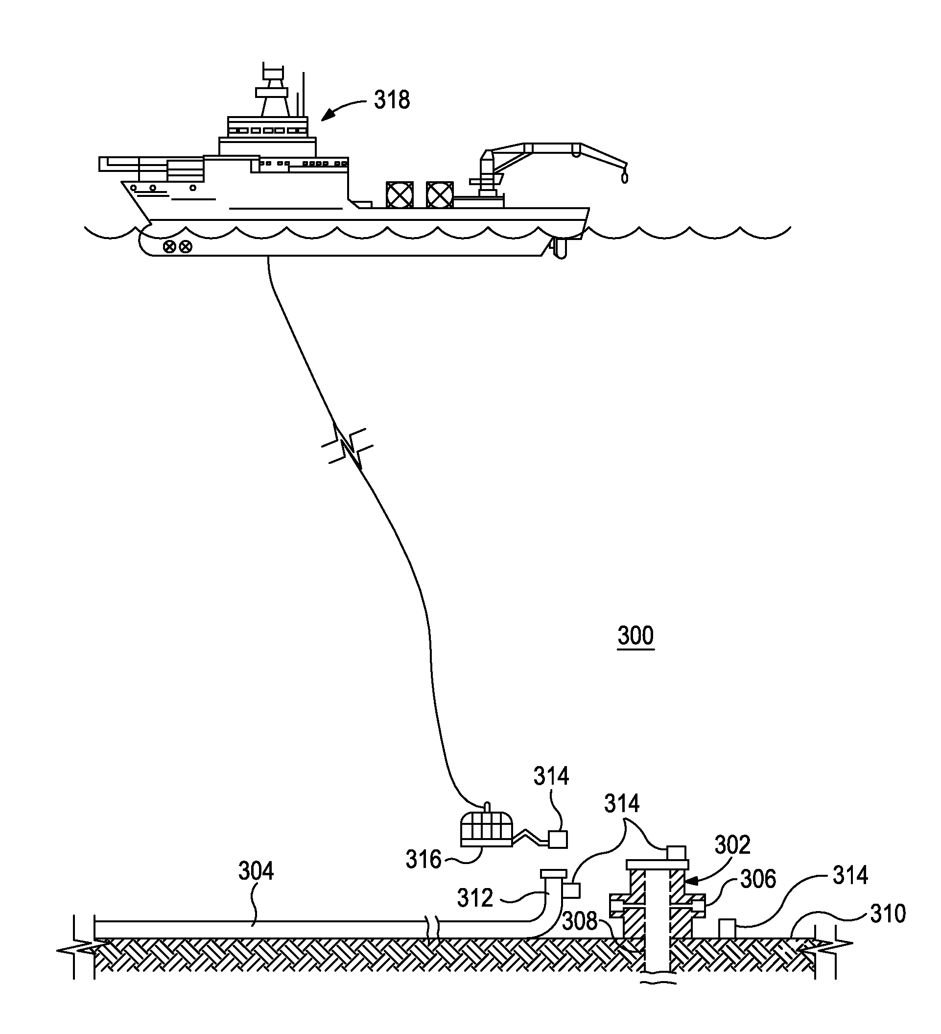
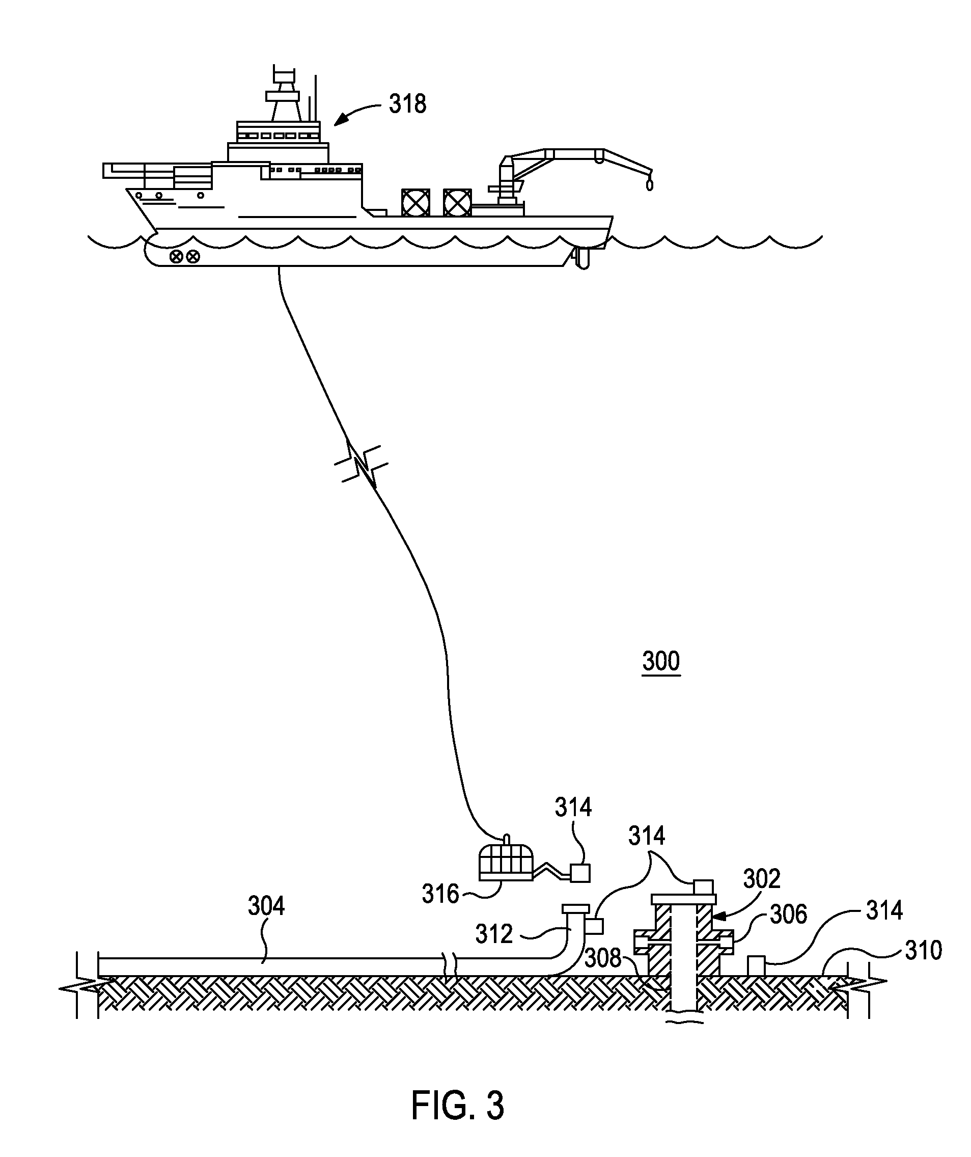
[0015]The present invention relates to optical analysis systems and, in particular, systems and methods for monitoring an oceanic environment for hazardous substances.

[0016]The exemplary systems and methods described herein employ various configurations of optical computing devices, also commonly referred to as “opticoanalytical devices,” for the real-time or near real-time monitoring of bodies of water, such as oceanic environments. In operation, the exemplary systems and methods may be useful and otherwise advantageous in determining the presence and / or concentration of hazardous substances that may exist around subsea oil and gas equipment. For example, the optical computing devices, which are described in more detail below, can advantageously provide real-time or near real-time monitoring of the water surrounding subsea equipment that cannot presently be achieved with either onsite analyses at a job site or via more detailed analyses that take place in a laboratory. A significan...


PUM


Abstract

Disclosed are systems and methods for monitoring an oceanic environment for hazardous substances. One system includes one or more subsea equipment arranged in an oceanic environment, and at least one optical computing device arranged on or near the one or more subsea equipment for monitoring the oceanic environment. The at least one optical computing device may have at least one integrated computational element configured to optically interact with the oceanic environment and thereby generate optically interacted light. At least one detector may be arranged to receive the optically interacted light and generate an output signal corresponding to a characteristic of the oceanic environment.

Description

BACKGROUND[0001]The present invention relates to optical analysis systems and, in particular, systems and methods for monitoring an oceanic environment for hazardous substances.[0002]As the oil and gas industry moves into deeper waters across the globe, the capabilities of subsea wellbore equipment and control systems are severely tested. In spite of significant advances in engineering, the complexity of the systems and the number of individual components in deepwater systems create numerous potential leak sites. Over the life of a subsea system, it is possible for a leak to occur in most of the components of a subsea well system. For example, connection leaks are often found in umbilical lines, hydraulic lines, control systems, flow hubs, casing, and similar components. Dynamic seal leaks are often experienced in surface-controlled subsurface safety valves (SCSSV), actuators, valves control systems and similar components. Static seal leaks are often seen in wellheads, packers, hang...

Claims


Application Information

Patent Timeline
IPC IPC(8): G06F19/00
CPCG01M3/22G01M3/38G03B17/08G03B2206/00G01N21/8507
Inventor TUNHEIM, OLAFREESE, ROBERT P.ABNEY, LAURENCE J.MACLENNAN, JAMES R.
Owner HALLIBURTON ENERGY SERVICES INC
Why Eureka
Try Eureka