Pedal simulator for active brake system

Active Publication Date: 2014-03-13
HL MANDO CORP
View PDF2 Cites 20 Cited by
  • Summary
  • Abstract
  • Description
  • Claims
  • Application Information

AI Technical Summary

Benefits of technology

[0009]Therefore, it is an aspect of the present invention to provide a pedal simulator for active brake system which may improve ped

Problems solved by technology

In the case that the pressure in the master cylinder changes during regenerative braking, the resulting force may be directly transferred to the brake pedal, thereby adversely affecting pedal feel.
When the pedal feel is degraded in this way, a large difference occurs between pedal feel that the driver receives in braking and the actual level of pressure applied to the brake disc of the brake pad in

Method used


Image

  • Pedal simulator for active brake system
  • Pedal simulator for active brake system
  • Pedal simulator for active brake system

Examples


Embodiment Construction

[0028]Reference will now be made in detail to the embodiments of the present invention, examples of which are illustrated in the accompanying drawings, wherein like reference numerals refer to like elements throughout.

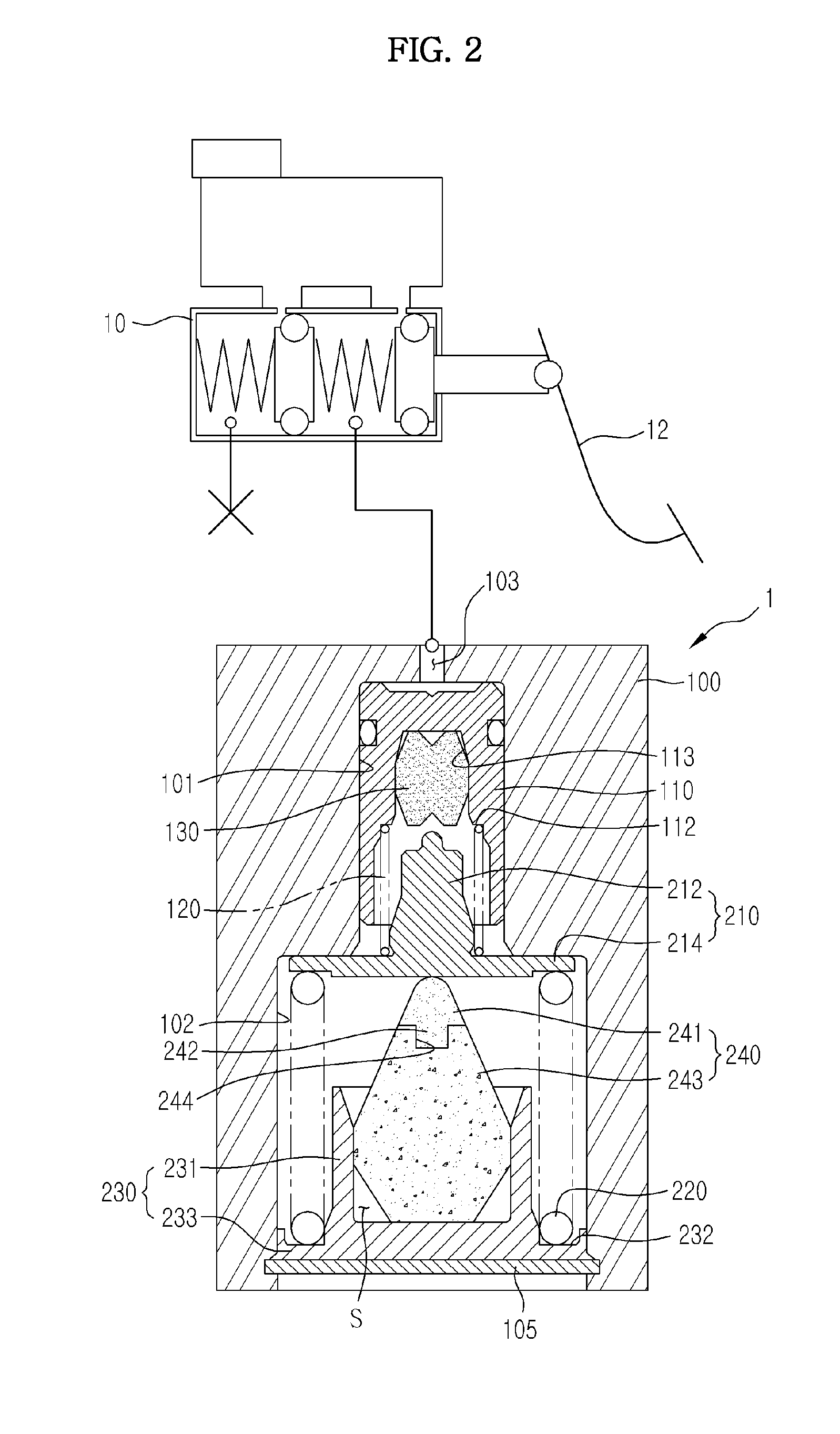
[0029]FIG. 2 is a view showing a pedal simulator for an active brake system according to an exemplary embodiment of the present invention.

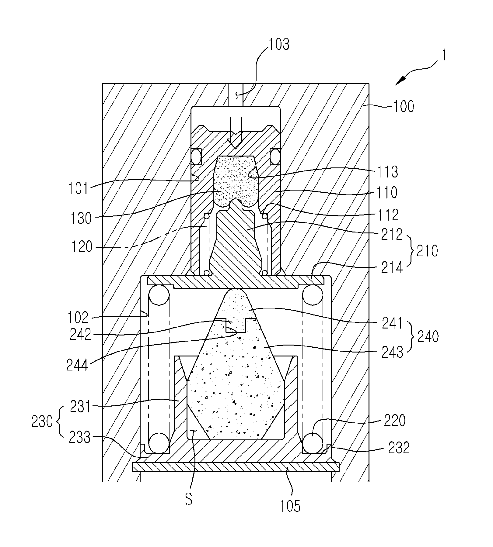
[0030]Referring to FIG. 2, the pedal simulator 1 includes a simulator block 100 installed at a master cylinder 10, which is caused to produce hydraulic brake pressure by a brake pedal 12, to accommodate oil from the master cylinder 10, and a first reaction unit and a second reaction unit installed at the simulator block 100 to provide pedal feel. Herein, the first reaction unit and the second reaction unit are formed in the simulator block 100 and arranged in series in a bore.

[0031]The simulator block 100 is provided with an oil hole 103 to allow inflow of hydraulic pressure from the master cylinder 10, and provided therein with a bo...


PUM


Abstract

Disclosed herein is a pedal simulator for an active brake system. The pedal simulator includes a simulator block provided therein with a bore, a first reaction unit including a first reaction piston slidably installed in the bore, a first damping member installed at the first reaction piston, and a first reaction spring compressed by the first reaction piston, and a second reaction unit including a second reaction piston provided in the bore to support the first reaction spring and slide in the bore, a damping housing connected to the simulator block to be spaced a certain distance apart from the second reaction piston, a second reaction spring installed between the second reaction piston and the damping housing to be compressed by the second reaction piston, and a second damping member installed in the damping housing to contact the second reaction piston. The second damping member is configured with an upper damper and a lower damper.

Description

CROSS-REFERENCE TO RELATED APPLICATION(S)[0001]This application claims the benefit of Korean Patent Application No. 2012-0100334, filed on Sep. 11, 2012 in the Korean Intellectual Property Office, the disclosure of which is incorporated herein by reference.BACKGROUND[0002]1. Field[0003]Embodiments of the present invention relate to a pedal simulator for an active brake system which may improve pedal feel.[0004]2. Description of the Related Art[0005]Generally, an active hydraulic boost (AHB) is a brake system that generates braking force when a driver pushes the pedal by sensing the push through an electronic control unit and supplying hydraulic pressure to the master cylinder through operation of a hydraulic pressure generation unit, thereby transferring hydraulic pressure for braking to a wheel cylinder of each wheel. In the case of such AHB, when the driver pushes the pedal during normal braking, a pedal displacement sensor senses the displacement of the brake pedal. The electroni...

Claims


Application Information

Patent Timeline
IPC IPC(8): B60T11/10B60T13/20
CPCB60T13/20B60T11/102B60T8/409B60T7/04B60T7/06B60T11/16
Inventor KIM, YONG KAP
Owner HL MANDO CORP
Why Eureka
Try Eureka