Lighting control system

a control system and lighting technology, applied in the field of lighting control system, can solve the problems of complicated verification procedure, inability to set parameters for a general user without expertise, and inability to meet the requirements of setting a plurality of parameters in the lighting system

Active Publication Date: 2014-03-13
PANASONIC INTELLECTUAL PROPERTY MANAGEMENT CO LTD
View PDF9 Cites 121 Cited by
  • Summary
  • Abstract
  • Description
  • Claims
  • Application Information

AI Technical Summary

Benefits of technology

[0013]In the present invention, the lighting fixture (2) transmits the identification information and the lighting information to the controller (3) by a visible light communication, and the display unit (35) of the controller (3) displays them (the identification information and the lighting information). Accordingly, a user can easily check whether or not each lighting fixture (2) is controlled in accordance with a set lighting condition. In addition, if the touch panel (36) on the image of the lighting fixture (2) displayed on the display unit (35) is operated, a lighting setting is performed to the lighting fixture (2) related to the image. It is therefore possible to enable a general user without expertise to easily and intuitively set a dimming level (ratio) and a color temperature of an illumination light.

Problems solved by technology

In the lighting system, there is, however, a problem that verification procedure is complicated.
The parameter setting is difficult for a general user without expertise.
In the lighting system of document 2, the user control device just has some command buttons, and accordingly the lighting system is not fit for setting of a plurality of parameters.

Method used


Image

  • Lighting control system
  • Lighting control system
  • Lighting control system

Examples


Embodiment Construction

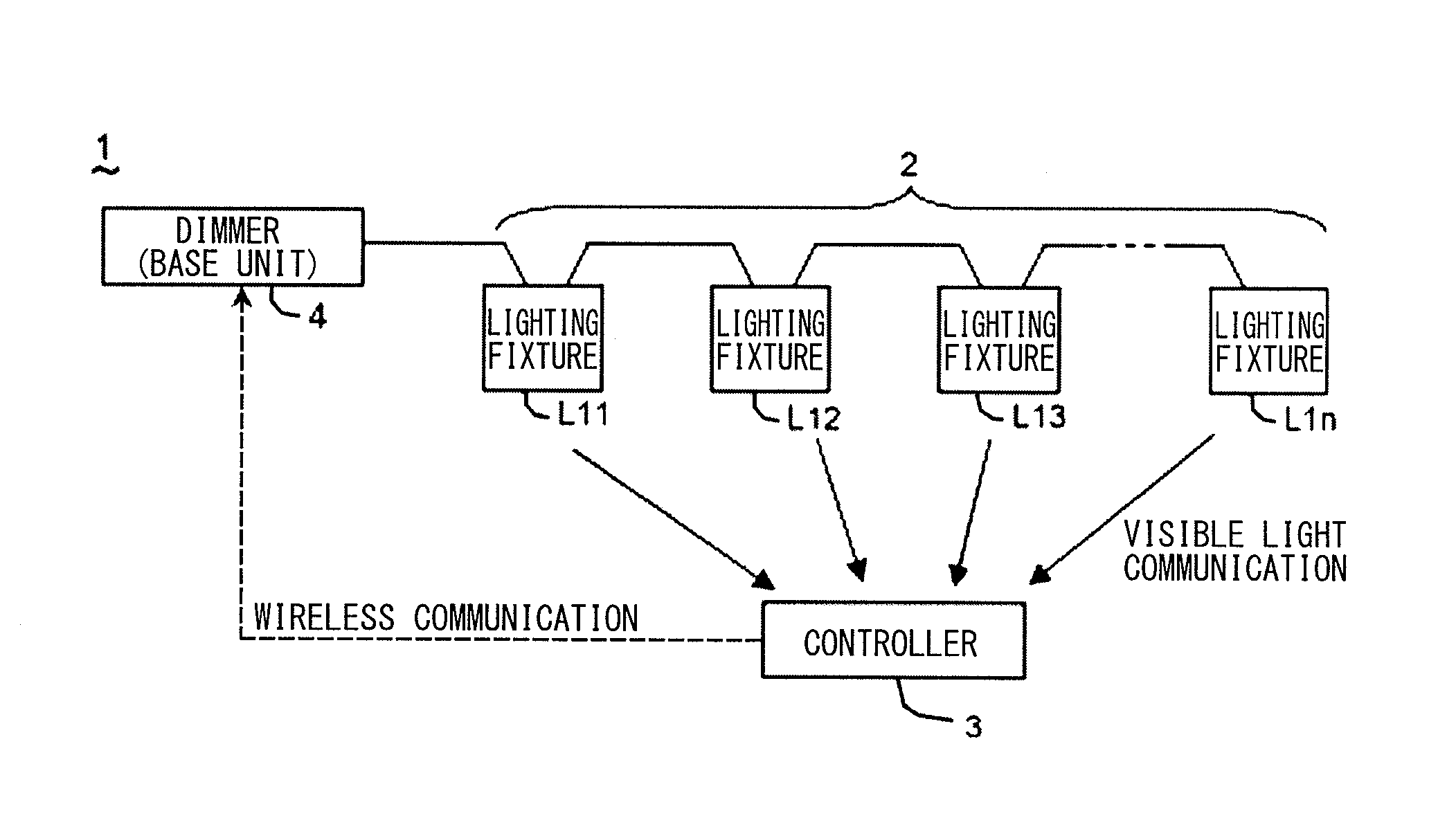
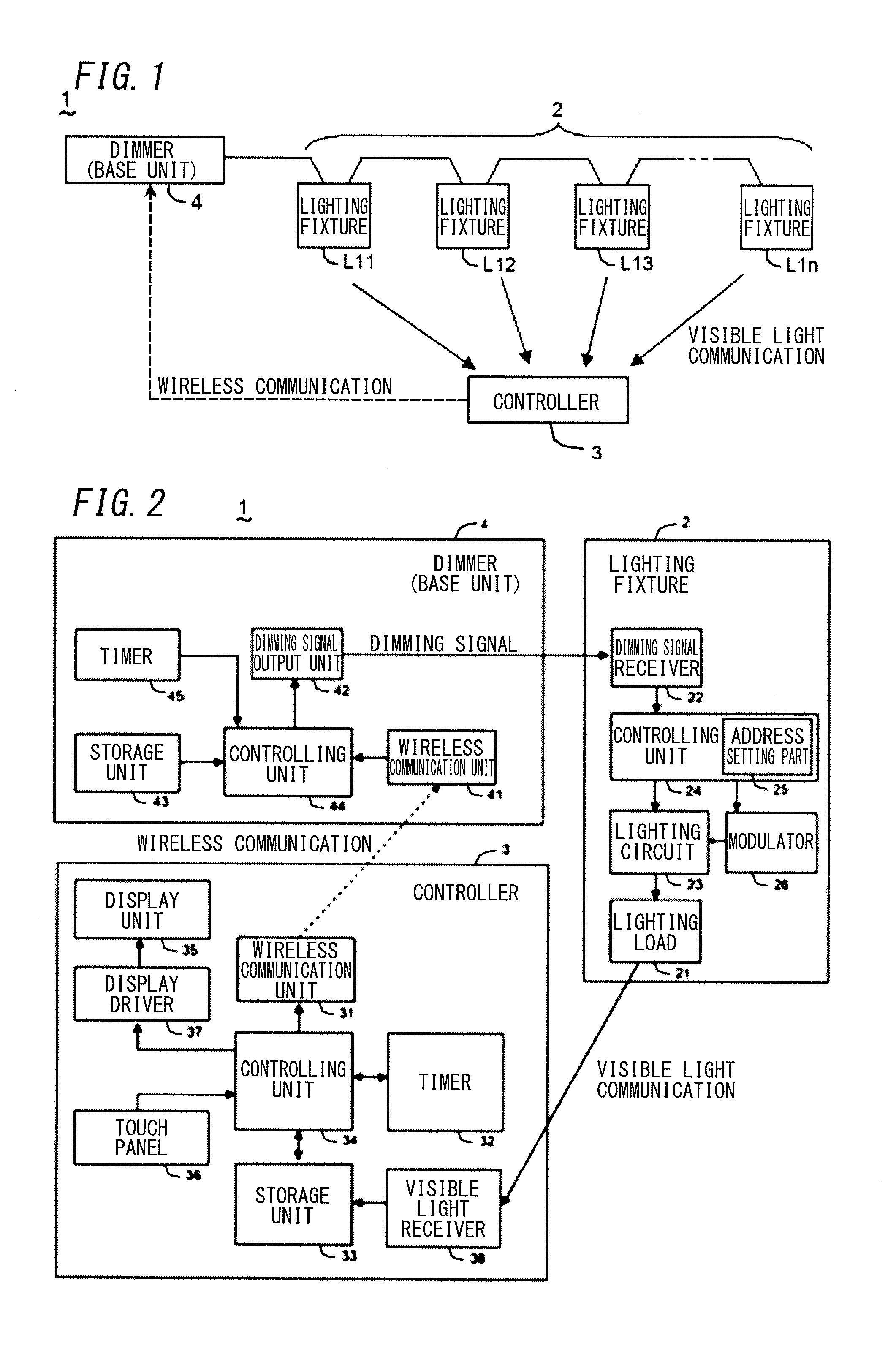
[0028]A lighting control system in accordance with a first embodiment of the present invention is explained with reference to FIGS. 1 to 12. The lighting control system (1) of the embodiment includes: a (at least one) lighting fixture (2) having identification information; a controller (3) configured to set a lighting condition for a dimming level and a color temperature of an illumination light of the lighting fixture (2); and a dimmer (4) configured to output a dimming signal for a lighting control of the lighting fixture (2) in accordance with the lighting condition set through the controller (3). The lighting fixture (2) includes: a lighting load (21); a dimming signal receiver (22) configured to receive the dimming signal from the dimmer (4); and a modulator (26) configured to modulate the illumination light of the lighting load (21) to superpose an information signal on the illumination light. The information signal contains an information set of the identification information...


PUM


Abstract

Lighting control system includes lighting fixture having identification information, controller for setting lighting condition for dimming level and color temperature of illumination light of lighting fixture, and dimmer for outputting dimming signal to lighting fixture. Lighting fixture includes dimmer for modulating illumination light to superpose thereon information signal containing identification information and lighting information of lighting fixture. Controller includes wireless communication unit for outputting control signal to dimmer, display unit with touch panel, for displaying image of lighting fixture, and visible light receiver for reading identification information and lighting information from information signal superposed on illumination light. Display unit is configured to associate identification information read through visible light receiver with image of lighting fixture to display image so as to reflect lighting information.

Description

TECHNICAL FIELD[0001]The invention relates to a lighting control system configured to control a dimming level (ratio) and color temperature of a lighting fixture.BACKGROUND ART[0002]Conventionally, there is known a lighting system configured to control dimming states (illuminance) of lighting fixtures according to a schedule set in advance to achieve labor saving and energy saving (e.g., Japanese Patent Application Publication No. 2002-373794 (hereinafter referred to as “document 1”)). In the lighting system of document D1, it is desirable that identification information such as an ID address or the like be previously set to each of the lighting fixtures connected to a main control device. In this case, it is possible to allow the lighting system to perform an ON-OFF control and an illuminance control (a dimming control) of each lighting fixture according to the schedule set in advance.[0003]In the lighting system, there is, however, a problem that verification procedure is complica...

Claims


Application Information

Patent Timeline
Patent Type & Authority Applications(United States)
IPC IPC(8): H05B37/02
CPCH05B37/02H04B10/116H05B47/165H05B47/175H05B47/19
Inventor NAGAZOE, KAZUFUMI
Owner PANASONIC INTELLECTUAL PROPERTY MANAGEMENT CO LTD
Why Eureka
Try Eureka