Device for determining the 3D coordinates of an object, in particular of a tooth

a technology for determining objects, applied in the field of scanners for scanning objects, can solve the problems of certain difficulties in the oral cavity of patients, the 3d coordinates of objects located in difficult to reach regions,

Inactive Publication Date: 2014-03-13
CARL ZEISS OPTOTECHN GMBH
View PDF8 Cites 11 Cited by
  • Summary
  • Abstract
  • Description
  • Claims
  • Application Information

AI Technical Summary

Benefits of technology

[0023]The markers present on the scanner initially are surveyed. Hence, the position of the markers on the scanner is known. The markers then are tracked by a tracking camera. By means of the tracking system, the location and rotary position of the scanner can be covered in the different shots. In this way, possibilities for combining the different individual shots of the scanner are improved or created.

Problems solved by technology

However, the detection of the 3D coordinates of objects located in regions which are hard to reach, i.e. in particular of teeth in the oral cavity of a patient, involves certain difficulties.

Method used


Image

  • Device for determining the 3D coordinates of an object, in particular of a tooth
  • Device for determining the 3D coordinates of an object, in particular of a tooth
  • Device for determining the 3D coordinates of an object, in particular of a tooth

Examples


Embodiment Construction

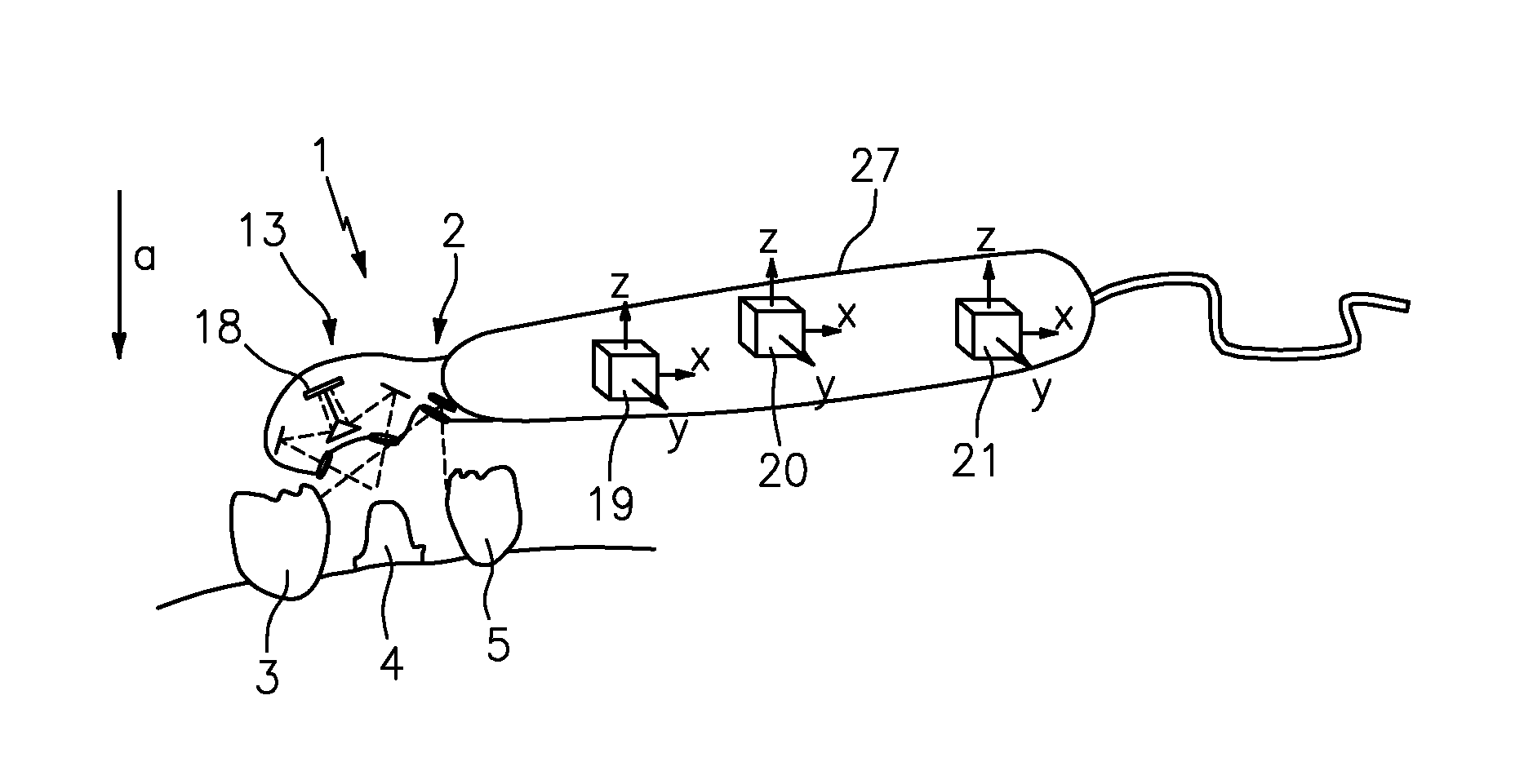
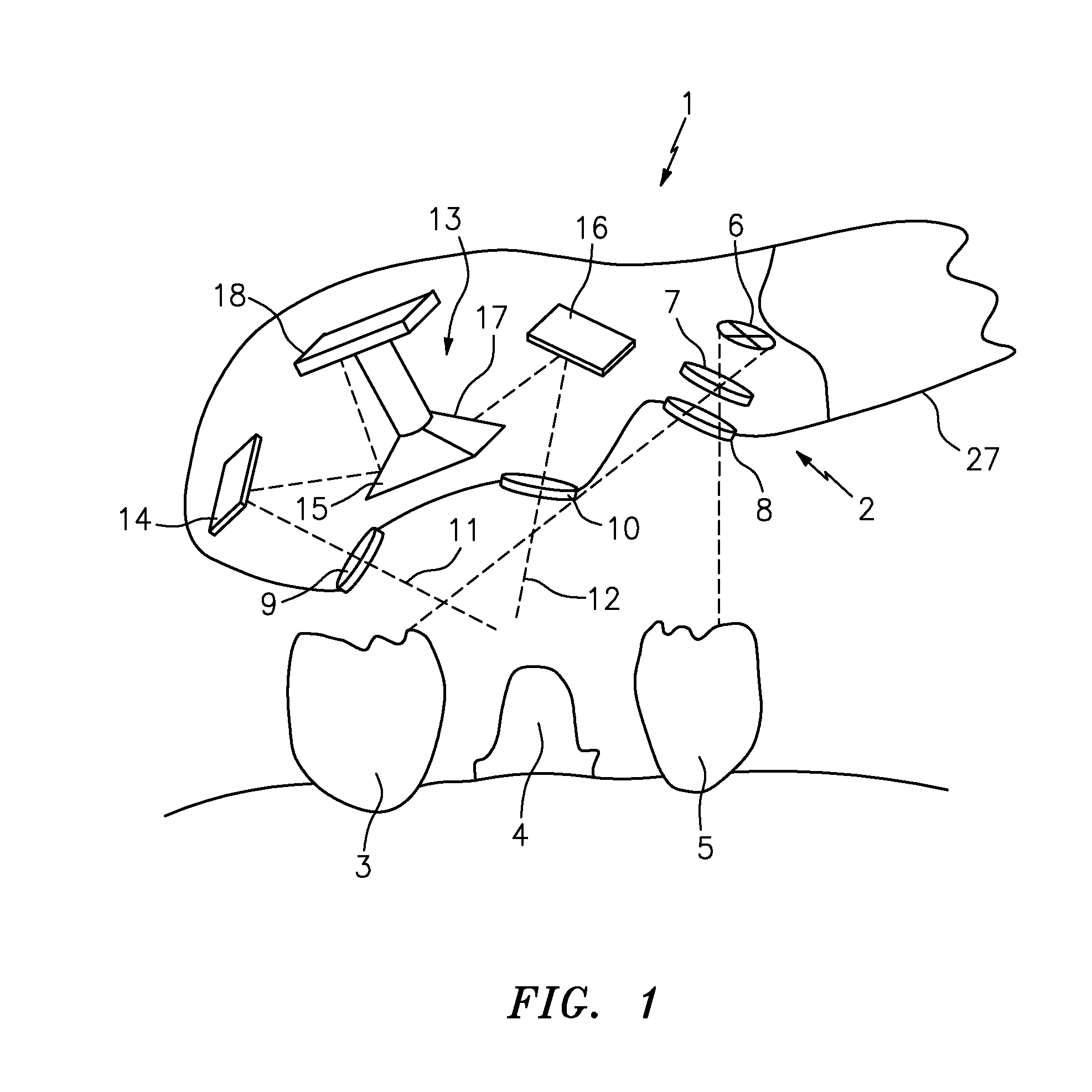
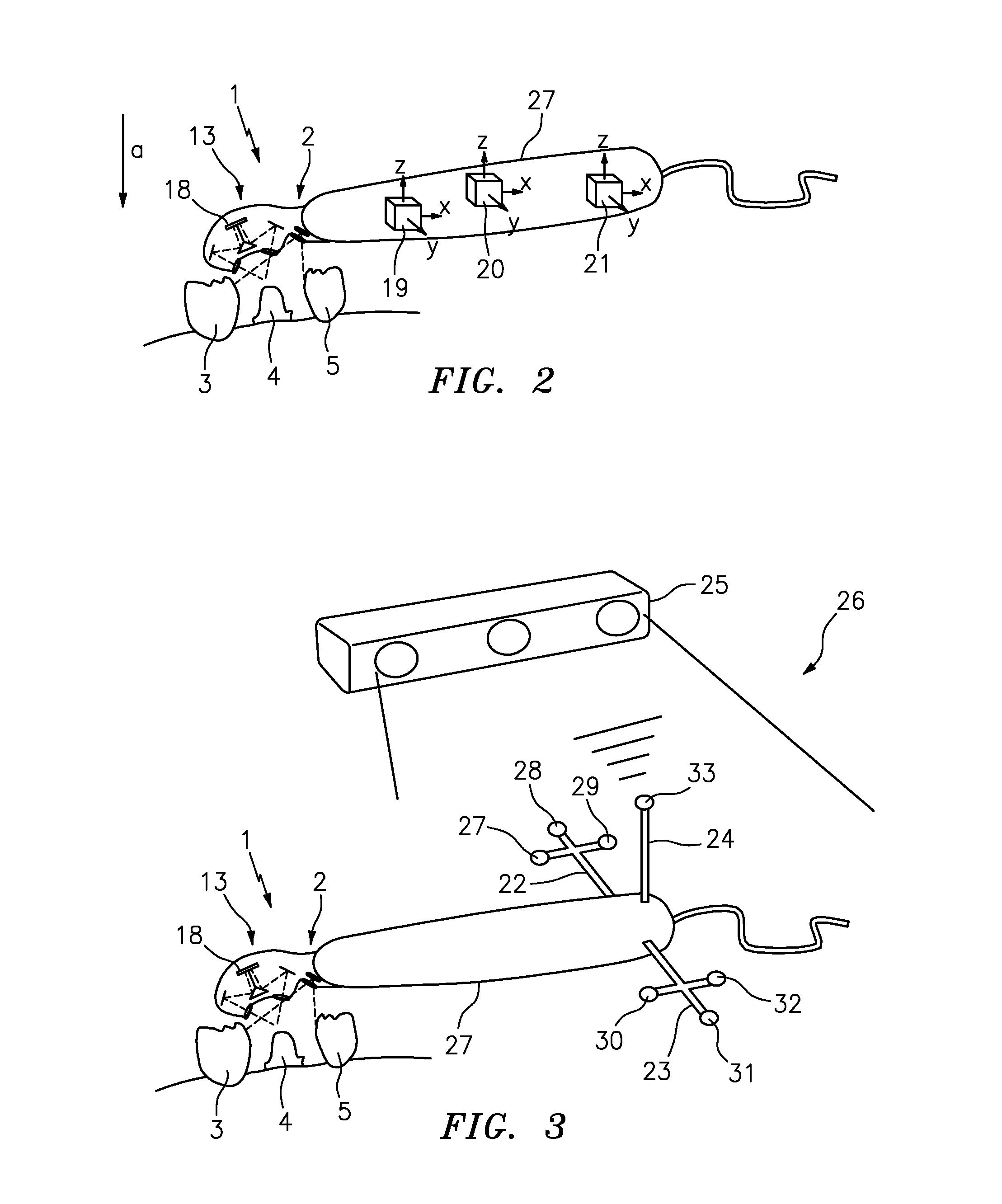
[0030]FIG. 1 shows a scanner 1 which includes a projector 2 for projecting a pattern onto the teeth 3, 4, 5. The tooth 4 is ground, the adjacent teeth 3, 5 are not ground and form the surroundings of the ground tooth 4. The projector 2 comprises a light source 6, a pattern transparency 7 and a projection optics 8. The light source 6 can be a light bulb or an LED. Instead of the pattern transparency 7 a transmitted-light LCD can also be used, which can be activated for forming a pattern. The pattern can, however, also be projected by means of a DMD or LCOS method.

[0031]In the scanner 1, a first imaging optics 9 and a second imaging optics 10 furthermore are provided, which are spaced from each other and whose optical axes 11, 12 form an angle with respect to each other. The distances of the imaging optics 9, 10 and the directions of the optical axes 11, 12 are chosen such that they are directed towards a common region of the ground tooth 4.

[0032]The scanner 1 furthermore comprises a ...


PUM


Abstract

A scanner is used for scanning an object (3, 4, 5), in particular a tooth or a plurality of teeth or a dental cast. The scanner (1) comprises a projector (2) for projecting a pattern (7) onto the object (3, 4, 5) and a camera which comprises a recording optics and an image sensor (18). To improve such scanner, the recording optics comprises a first imaging optics (9) and a second imaging optics (10).

Description

CROSS-REFERENCE TO RELATED APPLICATIONS [0001]The present application is a continuation of co-pending application Ser. No. 12 / 228,917 filed Aug. 18, 2008, the contents of which are incorporated by reference herein.BACKGROUND OF THE INVENTION [0002]This invention relates to a scanner for scanning an object, in particular a tooth or a plurality of teeth or a dental cast, and a device for determining the 3D coordinates of an object, in particular of a tooth or a plurality of teeth or a dental cast.[0003]Devices and methods for determining the 3D coordinates of an object are known already. EP 299 490 B2 describes a method for making a dental prosthesis, in which contour lines on the ground tooth and its surroundings are produced, the lines are detected with an optoelectronic means, in particular a video camera, the detected values are entered in a computer, and the three-dimensional structure of the tooth and the dental prosthesis is calculated. By means of the structure thus calculated...

Claims


Application Information

Patent Timeline
Patent Type & Authority Applications(United States)
IPC IPC(8): G01B11/25
CPCG01B11/2545G01B11/03G01B11/2518A61C9/0053G01C11/02
Inventor GANDYRA, MICHAEL
Owner CARL ZEISS OPTOTECHN GMBH
Why Eureka
Try Eureka